H. G. Dietz
http://aggregate.org/hankd/
Department of Electrical and Computer Engineering
Center for Visualization & Virtual Environments
University of Kentucky, Lexington, KY 40506-0046
Initial release: April 10, 2006
This document also is available with higher-quality images as a 66,005,972-byte 28-page PDF. Either version should be cited using something like the bibtex entry:
@techreport{peepfish20060410,
author={Henry Gordon Dietz},
title={Fisheye Digital Imaging For Under Twenty Dollars},
month={Apr},
year={2006},
institution={University of Kentucky},
howpublished={Aggregate.Org online technical report},
URL={http://aggregate.org/DIT/PEEPFISH/}
}
The concept of a low-cost fisheye digital camera is very appealing. Unfortunately, fisheye lenses still carry the price premiums associated with limited market ``specialty'' item status. This paper describes how a commodity door peephole can be used as a fisheye converter lens, thus bringing the total parts cost of a serviceable digital camera with a fisheye lens to under $20 US.
|
In the past, fisheye photography had been considered primarily a ``special effect'' to be used sparingly for its ability to provide a distorted perspective. However, fisheye imaging recently has become of much greater importance. There are two major reasons:
In this paper, we detail an innovative approach by which digital fisheye cameras capable of both still and motion capture, either independent of a computer or under wired computer control, can be assembled for a total cost of less than $20 US. This cost is street retail pricing, does not reflect any discounts, and each of the parts can be obtained from multiple vendors.
The primary trick is the sub-$4 fisheye lens, described in Section 2. This lens is usable with a wide variety of cameras; because the fisheye image quality is better than the sub-$15 camera can capture, a variety of somewhat more expensive alternatives are discussed in Section 3. Section 4 is dedicated to a particular sub-$15 digital camera, built by SAKAR, that works fairly well with the fisheye lens, is widely available, and is well supported by free software under LINUX. Section 5 details basic image capture using the SAKAR camera under LINUX. Section 6 discusses a few methods for digitally enhancing image quality. The conclusion and sample photos are given in Section 7. Acknowledgements, disclaimers, and references appear at the end of this report.
Before discussing fisheye lens options, it is useful to define what ``fisheye'' means. Although the name is associated with ultra-wide-angle lenses (dictionary.com defines it as being ``a photographic lens that covers an angle of about 180 degree, producing a circular image''), fisheye is more correctly a lens using a particular type of projection in which the image has what could be described as severe barrel distortion. Objects imaged at greater angles span fewer pixels, whereas rectilinear wide-angle lenses cause objects imaged at large angles to be spread across more pixels. Thus, fisheye projection allows any angle of view. Whereas it would take infinitely many pixels to use a rectilinear projection for an image with a 180 degree angle of view, a fisheye simply produces a circular image when the view angle approaches or exceeds 180 degree. More or less extreme view angles can be implemented with a fisheye projection, and the naturally circular image can be cropped to a rectangle. A fisheye lens whose field of view is given a rectangular crop often is called a ``full frame fisheye'' since film and image sensors generally are rectangular.
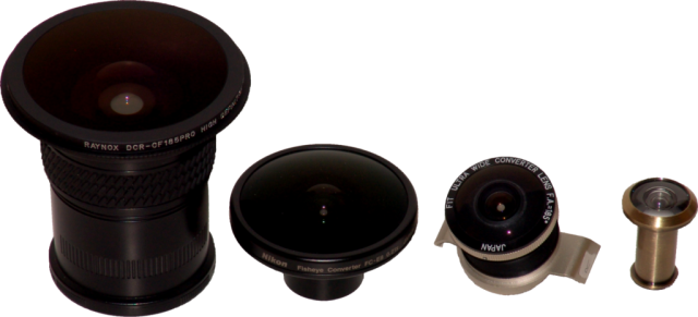
For film and digital cameras alike, fisheye lenses tend to be expensive niche-market items. In this technical report, we will limit ourselves to alternatives that are truly fisheye lenses, as opposed to things like photographing reflections in convex mirrors (which will be the topic of another technical report). The fisheye lens options fall into just a few general categories:
There is a commodity market for a specific type of fisheye lens: door peepholes. Door peepholes were not designed to be camera lenses, however, most devices for human viewing are designed to produce their images at an apparent viewing distance comfortable for humans - which is a fair approximation to what a converter lens does. Thus, it should be possible to use a door peephole as a converter lens. Converter lenses avoid the problems involving sensor size and critical alignment of the focal plane, and they can be literally taped or hot-glued onto nearly any base lens.
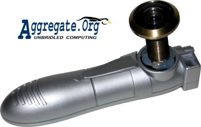
Our $4 (really $3.20 from several online vendors) fisheye converter lens is shown in Figure 3. Different peepholes have very different characteristics. Some are made of plastic, but this one is a very solid glass and metal construction. That said, we're not talking about a multicoated optic here, and lens flare (always a serious problem for fisheye lenses) can be severe. It is common that the finish on the outside also is used on the inside, so bright shiny finishes might imply even more internal reflections than darker finishes like antique brass. Careful positioning of light sources in the image is needed to minimize a variety of annoying internal reflections. Alternatively, if the camera and light source positions will be fixed for many images, it is possible to digitally correct lens flare using essentially the same approach described in Section 6.1 for removing fixed-pattern noise.
Angle of view is always wide, but 132 degree is common; this particular fisheye door peephole quotes a 200 degree viewing angle. In practice, it does not provide a 200 degree view when used as an adapter lens, but it does exceed 170 degree on most cameras for which it is a suitable attachment. The limiting factor on viewing angle seems to be the metal ring around the lens front.
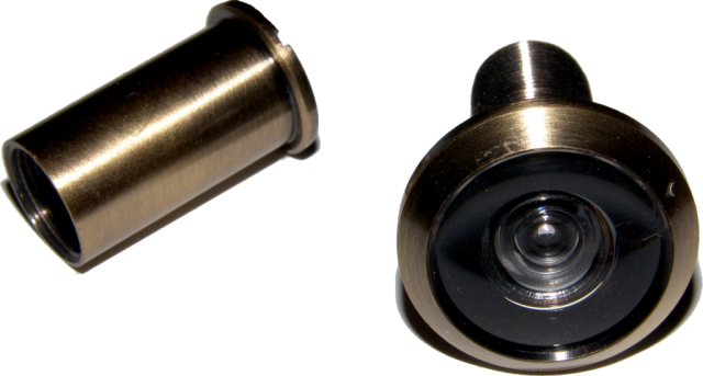
Another issue is the diameter of the eyepiece. The DELTANA peephole fits in a 5/8 inch (16mm) hole, in which the eyepiece is fairly deeply recessed. It is designed to fit doors 1-3/8 to 2-1/4 inches thick, which means that the shaft of the unit is 1-3/8 inches long when fully screwed-in; the rear viewing element is recessed by about 1/2 inch within this shaft. That's a fair amount, so the fisheye image is smaller than ideal for some cameras, but a hacksaw easily can cut-off most of the last 1/2 inch of threaded tube, thus slightly increasing the image size. To trim the lens shaft with a hacksaw, it is easiest to build a simple jig by drilling a hole in a piece of scrap wood whose thickness matches the amount of shaft that should remain; push the lens in the wooden jig and hold the hacksaw blade against the wood while cutting in order to get an even cut. Any remaining burr or unevenness can be quickly eliminated using a power sander. The only problem with this procedure is that the fine metal particles are remarkably good at finding a way to get between the lens elements, where you can't easily clean. Because of this complication, the camera mounts discussed in this paper all use the unmodified full-length shaft.
Interestingly, brief tests substituting a narrower-shaft 190 degree bright brass fisheye produced very similar results with the SAKAR digital camera discussed in this report. The narrower shaft was compensated for by the fact that the threaded shaft was much shorter, resulting in a smaller and lighter lens with virtually the same image circle diameter. Lens flare within the image circle was not significantly worse than for the darker finish peephole, but reflections outside the image circle covered most of the frame... which oddly enough may have the beneficial side effect of resulting in better autoexposure in difficult lighting. The field of view was slightly less than that of the 200 degree peephole. Then again, this peephole cost nearly $7. In summary, lots of peepholes probably will work with only minor quality differences, and our bias toward the DELTANA in this report is due to its wide angle of view, build quality, and low cost.
It is appropriate to note that the concept of using a door peephole viewer as a fisheye converter is not uniquely our idea, but is rather obvious to anyone who has ever looked through a peephole. A nice little description of using a peephole mounted in a lenscap with a zoom lens on an SLR is given by Dave Nance at his WWW site[6], and the same trick also is mentioned in various other places [2,5]. A peephole also has been used as a viewfinder for a non-SLR camera modified to use a ``real'' fisheye lens[3]. Our contribution is primarily in the details of using a peephole with an inexpensive digital camera.
A peephole fisheye can be used as a converter lens on any of a wide range of cameras. Of course, that does not mean it will work on every camera and, in fact, it doesn't work on most. Usually the problem is a standard lens that either has a front element with too large a diameter or has focal properties that prevent the peephole fisheye converter from producing a good image. The first problem is usually obvious from camera specifications on the web, but the second is very difficult to determine without physically testing the camera. Ironically, slightly longer focal length lenses tend to work better because they give a larger fisheye image.
Although most of this paper centers on using the $15 SAKAR digital camera (discussed in Section 4) to capture the fisheye images, the peephole fisheye image quality is somewhat better than that camera can capture. Thus, it makes sense to try some more expensive, but higher-quality, digital cameras. The following cameras have been tested.
A quick check in a local retail store confirmed that the peephole fisheye might be usable with this 3MP digital camera which costs less than $150. Test image edges appeared excessively soft (a focus problem?), but the camera's zoom range easily goes from circular to full-frame fisheye. The primary issue is that the A410 has a retracting lens which would make mounting the fisheye awkward; the best solution probably would be to build a mount that fits onto the camera body and allows the peephole fisheye lens to be somewhat loosely fitted to that mount so that the fisheye can slide to rest up against the lens front, but any zooming or focus movement of the lens will not encounter significant resistance from the fisheye mount. See the OLYMPUS FE-100 description in Section 3.5 for details about this type of mount.
The CANON G series of compact cameras nearly defined ``prosumer'' digital cameras for half a decade; they all have full manual controls, RAW sensor file formats, and the ability to use a variety of add-on lenses - including some of the lens listed in Section 2.1. Quick tests with a G1 reveal the peephole fisheye is not effective with the G1 and probably should not be used with any of the G series cameras. The primary problem is the large front element of the lens; the image circle is either too small or vignetting is a problem.
Although the front element of the lens is slightly larger than the peephole shaft, it is only larger in the horizontal in order to accommodate the 4x3 frame width. This 7MP digital camera is able to capture both circular and full-frame fisheye images using the peephole lens, although full-frame requires some digital zoom. As with the CANON A410 and OLYMPUS FE-100, mounting the fisheye is awkward because the lens retracts.
The S70 is fairly expensive, so if you can afford it, you probably can afford a better fisheye conversion lens and a camera that it can mount on. However, this compact camera is a bit of a wolf in sheep's clothing, with excellent resolution and full manual controls, making it arguably the highest-quality imaging system that you could put behind a peephole fisheye.
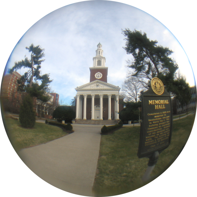
In order to get a good fisheye image size, the S70 lens needs to be zoomed in quite a bit, which in turn requires setting macro mode for this peephole lens. Image contrast using the peephole fisheye is markedly lower than the normal lens provides, and sharpness is not consistent across the field. Some of the most gross defects in the test shots probably are due to very imprecise test lens mounting, but it is pretty clear that the fisheye lens is being pushed well past its quality limits. The 4x3 7MP sensor of the S70 produces circular fisheye images that contain up to about 4M active pixels. Test images from the S70, like the one shown in Figure 4, suggest that a 4x3 sensor resolution between 2MP and 3MP would deliver all the image quality that the peephole fisheye lens has to offer.
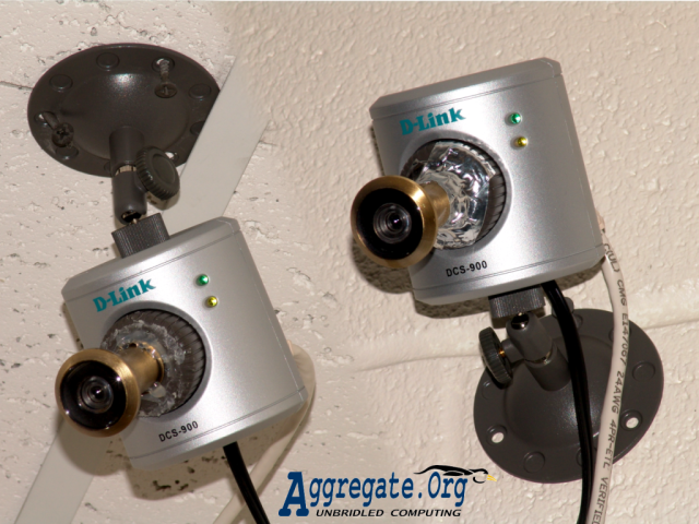
This is a very popular and fairly cheap (less than $100) Ethernet network camera with 640x480 sensor resolution. As a network camera, it doesn't need a computer in order to serve images or low-framerate video. The DCS-900 hardware and firmware is quite stable, and it is trivial to obtain images from it under Linux using either wget http:/camera_address/IMAGE.JPG or using the freely-available MCAMIP software[7]. On the downside, image quality of the DCS-900 is fairly poor, especially in low light (but not markedly worse than its competitors).
Mounting the peephole fisheye lens is awkward because the DCS-900 has a large, gently-rounded, focus ring that gives no reference points for centering the mount. Here's the process that we have found to be effective:
The peephole fisheye is usable, but awkward, with this 4MP digital camera which costs less than $150. General properties and performance are very similar to those observed with the CANON A410, although fisheye image quality might be slightly more consistent across the image circle using the OLYMPUS FE-100. Certainly, the FE-100 is not the limiting factor on image quality - the peephole is.
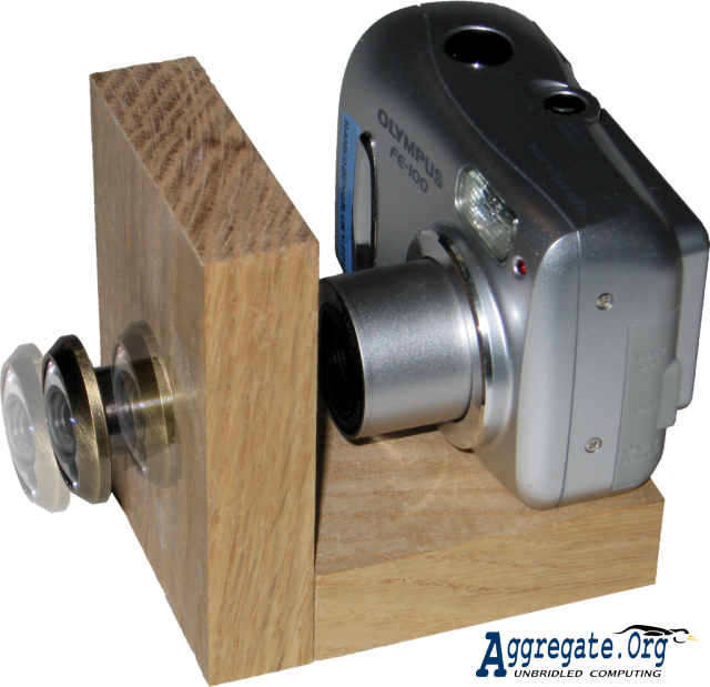
The primary complication is that the FE-100 has a retracting lens which makes mounting the fisheye awkward. One could use a lenscap-like mount, but the cap would need to be a fairly tight fit on the front of the lens barrel; that would offer significant resistance to zoom, focus, or lens retraction, potentially damaging the lens motor drive system. The best solution probably would be to build a mount that fits onto the camera body and allows the peephole fisheye lens to be somewhat loosely fitted to that mount so that the fisheye can slide to rest up against the lens front, but any motorized movement of the lens will not encounter significant resistance from the fisheye mount. Such a mount is easy to make by taking advantage of the fact that the peephole is designed to mount in a relatively thick door; mounting in a thinner piece of wood allows the peephole to slide freely within its mounting hole. The mount also keeps the peephole from sliding all the way out and dropping on the floor.
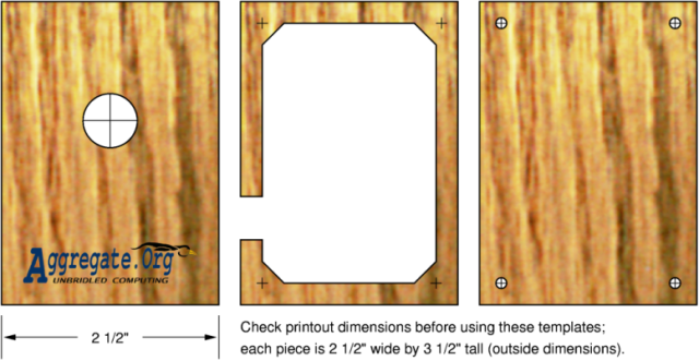
A prototype version of this ``sliding'' lens mount is shown in Figure 3.5. It is constructed as a wooden ``L'' consisting of two pieces: a front and a base. The front piece is drilled to the outside dimension of the peephole sleve so that the peephole will be able to freely slide in the hole. The base is drilled with a hole lining-up with the tripod mounting threaded socket of the camera, which will be used to connect the mount to the camera. The ``L'' shape is made rigid and permanent by your favorite type of joinery; anything from screws to dovetailing is ok, but I'm partial to biscuit joinery. The key is to make sure that when the camera is mounted, the fully-extended lens still has a small gap between it and the back of the maximally-forward sliding peephole.
The SONY DSC-F828 is a serious 8MP machine with a zoom lens spanning the 35mm equivalent of 28mm to 200mm; thus, it makes a good vehicle for testing the ``mount a peephole in a zoom lens lenscap'' concept so often discussed for conventional SLRs. The peephole fisheye is not effective with this SONY. The primary problem is the large front element of the lens; the image circle is either too small or vignetting is a problem.
It might be viable to use multiple fisheyes for simultaneous stereo fisheye image capture, but that is getting a bit too far out for this technical report....
Although they are analog NTSC cameras, not digital, a variety of wired and wireless video cameras sold by www.x10.com seem to work very well with the peephole fisheye. When they are on sale, these cameras can be quite cheap... but probably not under $20. Of course, the analog video signal can be digitized using any of a wide range of capture hardware, but that costs money too.
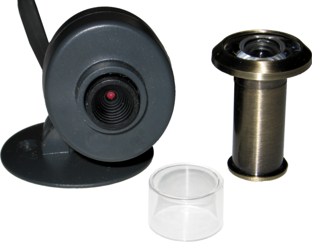
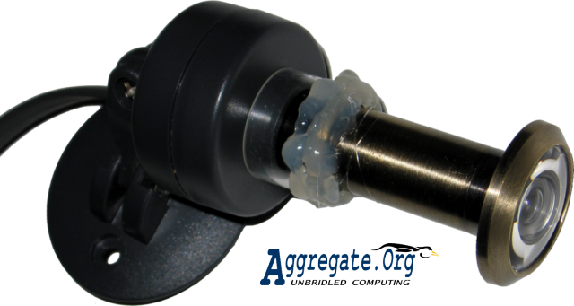
Mounting the fisheye lens is very simple. The XCams that we have tested all come with a clear plastic lens protector that fits tightly over the lens to give some degree of weatherproofing. As can be seen in Figure 8, that lens protector is just slightly larger in diameter than the barrel mount for the peephole, so it is a simple matter to glue/tape the two together in nearly perfect alignment, as shown in Figure 9. Adjusting the focus is a bit awkward because the focus cannot be adjusted with the lens protector (and hence the fisheye) on the camera, but focus isn't really critical. The fisheye image circle using a standard XCam just happens to be nearly the ideal size - just slightly less than the full frame height. Another happy surprize is that the autoexposure logic of the XCam, which normally is a bit too dramatic in its transitions when lighting changes, seems to do a little better with the peephole fisheye mounted.
In addition to trying the B&W wired XCam shown in Figure 9 directly, it also was tested in a rather scary configuration. Carefully sealing the camera and lens using plastic wrap, the camera was mounted on the end of a 10' long PVC pipe and used to feed live video inspecting the underwater vegetation and fish population in Dietz's two half-acre ponds. Certainly, there are safer ways to waterproof a camera, but the point is that the peephole fisheye worked exceptionally well underwater. The wide viewing angle and huge depth of field really help; it was quite surprising to see adult largemouth bass swiming so close by the lens. A couple of years ago, the same camera was tested in a kludged underwater housing using only the normal lens, but no useful images were seen from it then.
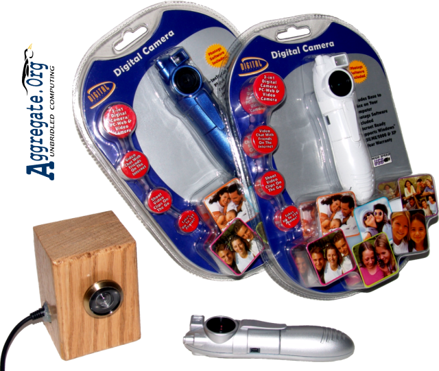
Although $15 sounds like very little money to pay for a combination digital still camera, movie camera, and USB webcam, a trip to WALMART yields not just one, but two completely different choices. The first is a very cute ``keychain'' camera; it is surprisingly good in many respects. The other alternative is generally very similar in functionality, but is a ``pen camera'' configuration that is about twice as large as the keychain camera - mostly because it is powered by two AAA cells rather than one.
The $14.88 ``pen camera'' which is ``Item #82379'' from www.sakar.com is the one we'll use here. The unit in its retail packaging is shown in Figure 10. The body is plastic, in one of three colors: white, metallic gray, or metallic dark blue. There are no apparent differences between the different color models beyond the color of the plastic.
There are two fundamentally different approaches to mounting the fisheye converter on this camera: the easy way and the hard way. As is often the case, the easy way is every bit as functional as the hard way, but doesn't look as pretty. Actually, the easy way is slightly more functional. There also is a third way that's a minor variation on the hard way, most appropriate for robots, models, and kite aerial photography. I probably don't need to tell you this, but any of these mounting techniques is likely to void the manufacturer's warranty... so make sure the camera works before you modify it.
Before you begin to modify the camera in any way, you'll want to install the appropriate V4L2 device driver on your computer, as described in Section 5. That will allow you to test the camera and will help with alignment of the lens mount. Lens alignment is critical, and you can't get it right just by being careful. In fact, being careful to flatly center the peephole fisheye lens on the camera's base lens doesn't correctly align the lens - the base lens and sensor are not that precisely aligned to begin with. In fact, every one of the cameras we've checked looks downward by a significant amount. Thus, the only way to get a good optical alignment is to continuously check a live display from the sensor itself. You can do this via USB connection to a computer using any compatible V4L2 display program, such as XAWTV.
Unscrew the peephole fisheye lens from its threaded mounting sleve. The threading of the lens nests nicely inside the black plastic trim piece that goes over the base lens (as seen in Figure 12), but putting it in straight will not place the fisheye image anywhere near the center of the frame. Pivot and slide the fisheye lens around until the fisheye image is roughly centered in the video. First tack, and then generously hot-glue around, the bottom edge of the fisheye lens. You're done.
Everything about the camera will work precisely as it did before, but with an approximately 184-pixel diameter circular fisheye image roughly centered in the 4x3 frame. The circular image does fool the autoexposure, and the camera does not provide any exposure compensation mechanism. Fortunately, the exposures are still usable in typical indoor or low-light scenes, but the daylight behavior is often fairly severe overexposure. The only possible corrections are deliberately making the scene darker (e.g., using a neutral density filter) or introducing stray light to brighten the area outside the image circle. Stray light could be introduced either by letting daylight leak around the fisheye or by mounting a LED to light the area... or simply by using a peephole with a bright finish that causes the area around the image circle to be largely filled with stray reflections. The problem has not been severe enough for us to bother with any of those remedies. Actually, when the camera is first plugged into USB, the autoexposure system seems to initially give a very low contrast image which is not overexposed, but the autoexposure kicks in as soon as the light level changes... if we can figure-out how to get the low-contrast behavior on demand, we will post that as a fix to the exposure problem.
Don't do this. Really. Just don't. You've been warned.
Still with me? Ok. Let's do some unnecessary surgery.
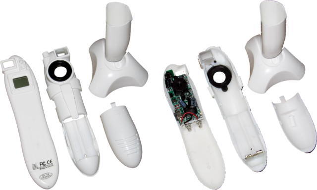
Although it isn't necessary to open the camera in order to mount the fisheye converter, you can get the converter slightly closer in that way. It also is useful to see what's really in there. The camera clearly is not intended to be taken apart. However, a little prying with a pocket knife easily breaks the camera into its front and back pieces. Figure 12 shows the pieces of the camera. The stand is really quite nice, although it has the same problem as so many other webcam stands: the stand easily can be tipped over by a slight tug on the USB cable. The plastic is not particularly impressive, but neither does it feel flimsy; the overall finish is quite pleasing. Anyway, we're not going to be using any of those pieces.
The construction inside, also shown in Figure 12, is equally simple, yet effective. The black ring around the lens, which was the only thing keeping the fisheye converter away from the lens, turns out to be held to the outer frame with a single screw - it easily could be removed and the camera reassembled. While we're around the lens, it is worth noting that the lens isn't really fixed focus! Unfortunately, it seems that the lens was factory-adjusted to an optimal single focus point and then the plastic adjustment thread was touched with something like the tip of a soldering iron to lock it into place... it will not be easy to restore the ability to focus. The lens assembly is apparently mounted to the circuit board using a couple of screws. The battery compartment rather straightforwardly holds two AAA cells to serve as a 3V supply, but it is worth noting that the camera draws its power entirely from the USB host while it is plugged in. You do not even need batteries in the unit for USB-connected operation.
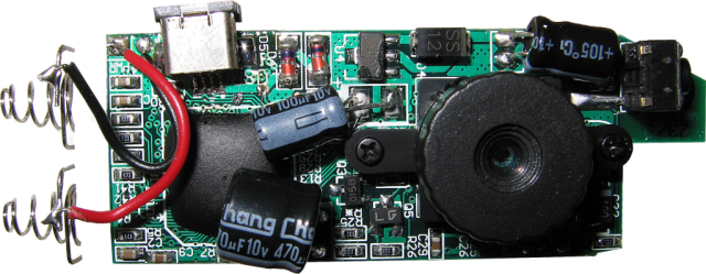
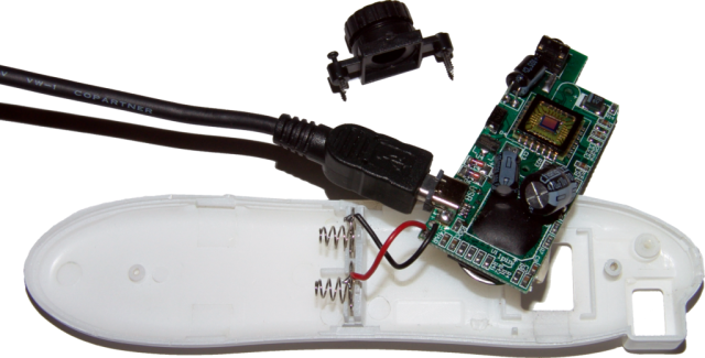
Let's take a closer look at the circuit board, shown in Figure 13. It's compact and fairly well made. It would be straightforward to replace the two AAA cells with an alternative power source by rerouting the red and black wires on the left side of the board, which might not be a bad idea given the fact that this camera has no flash memory. All your photos are stored in SDRAM which is corrupted if power fails. The non-standard USB connector at the top left is only a minor annoyance; the camera comes with an appropriate cable. The top right is occupied by a microswitch that serves as the shutter release; it also looks like it would be easy to rig an external circuit to serve as a remote trigger for image capture. To be precise, while the camera is running off USB power, there is 3.2V across the shutter microswitch... and 3.2V also is seen across the battery terminals while USB powered. One could use the battery terminals as a 3.2V power source for USB-powering something like a LED or two... either to light the scene or to provide exposure compensation (as discussed in Section 4.1).
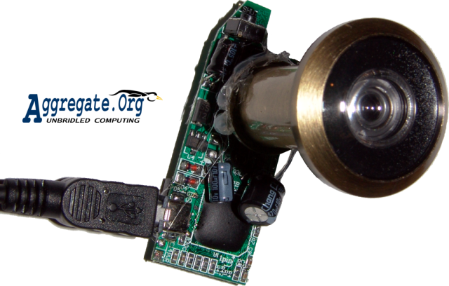
The lens that is apparently screwed to the camera circuit board with two very small phillips-head screws actually is screwed through the board rather than to it. Those two screws not only hold the lens in place, but also are the mount for the entire circuit board. Thus, if you unscrew the lens, you will find that the entire board comes free; further, when free from the case, there is nothing to screw into to hold the lens in place. Figure 14 shows the lens and board removed from the case. It is quite easy to get to the raw sensor if we want to use a different lens with the board - it is just a mounting problem.
Fundamentally, we want to mount the fisheye converter to that dinky little base lens... but again, you can't really just do that. First, there isn't much to mount to. Second, even if you did, there is still that alignment issue, which means a simple straight mounting wouldn't give the desired results. Third, we don't have a good way to mount the base lens back on the sensor board. Yuck. Fortunately, hot glue can hide a multitude of sins.
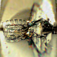
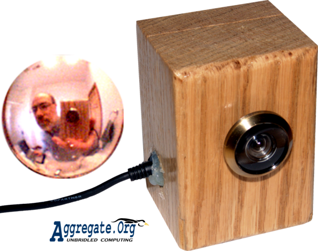
We'll solve the mounting problem by redefining the problem: rather than mounting the lens to the sensor board, we'll mount the lens in a block of wood and then mount the sensor on the same block. So, here's the full procedure to build the really cool looking ``fisheye webcam in a block of wood'' shown in Figure 1:
|
It is useful to note that the hard way to mount the lens to the camera also provides an excellent guide for how to mount the lens for use inside robots; on model cars, boats, or aircraft; or suspended from a kite for remote-controlled aerial photography. If you already have a structure to mount on, just take the camera board and lens (as shown in Figure 16) and install that as a module. In particularly weight-critical applications such as model aircraft, it also may be advisable to cut the fisheye lens barrel shorter and not use the mounting sleve at all.
The camera either can be powered via a USB connection or the leads that originally went to the batteries can be used to connect to an approximately 3V DC power source available on the device. Keep in mind that the camera image storage is volatile memory - if it loses power before you hook-up a computer, there will not be any images there to download. If there is no USB-capable computer onboard, the shutter can be triggered using a connection paralleling the shutter microswitch. The only additional complication is that you may need to turn the camera on (it turns itself off after a timeout period) by using a connection paralleling the microswitch on the rear of the board.
The $14.88 pen camera comes with PHOTAGS EXPRESS software for WINDOWS on a CDROM and a printed user manual (which also is available online from www.sakar.org). However, we can't do much with PHOTAGS under LINUX and we want free access to source code, because we'll be modifying some of it. So, how do we talk to the camera?
Page 9 of the camera's manual gives a few interesting technical details:
Although it's difficult to be sure, it looks like the camera uses a controller chip very similar to the SQ905C[1]. It's a bottom-of-the-line chip, but really not too bad. Some of the specifications it lists are slightly different from those quoted in the manual, but we can pick-up one more specification: the sensor is typically about ISO 100. That number combined with a 1/6 second maximum exposure time and F2.4 lens pretty much explains the poor low light performance of the camera. Then again, the 1/15000 second shutter speed sounds great - although our tests have revealed that high shutter speeds result in spatio-temporal distortions similar to those caused by the moving slit of an SLR's focal plane shutter. The electronic shuttering of the CMOS sensor exposes the top of the frame significantly before the bottom of the frame, so fast horizontal motion of an object tilts vertical lines away from the direction of the motion. The effect is no worse than for many SLRs, but it wasn't something we expected.
Plugging the camera into a LINUX system, lsusb identifies it as ID 2770:9120 NHJ, Ltd Che-ez! Snap / iClick Tiny VGA Digital Camera. It is worth noting, however, that ``VGA'' it is not - the packaging lists a maximum resolution of 352x288, and that's the maximum that the camera delivers. More precisely, gphoto2 identifies the camera as an Argus DC-1510, and is able to download images taken by the camera or to directly capture and download a preview image. The preview image is not a scaled-down lower resolution, but neither is it 352x288; it is 320x240 cropped from the center 75.75% of the 352x288 field. That's a bit unfortunate in that the lens already has a fairly long focal length for its sensor size, so this cropping produces a somewhat telephoto image. Assuming the ``(54)'' in the manual was referring to the effective 35mm-equivalent focal length at 352x288, at 320x240 we have something over 70mm. For whatever reasons, slightly telephoto focal length lenses are a very common feature of cheap digital cameras and webcams. In any case, it does not cause a problem with the peephole fisheye lens.
A cool feature of cameras such as this is that they have a variety of operating modes; this one has four distinct functions that could have you plugging the USB cable into your computer:
The USB communication protocol for GPHOTO2 is contained in a user-level library called LIBGPHOTO2 which uses LIBUSB to do the low-level USB work. More specifically, LIBGPHOTO2 contains camlibs, and sq905 is the camera library that this camera uses. Because GPHOTO2 doesn't know what cameras you have or where they are connected, you either have to tell it or, more commonly, it goes looking for an appropriate device each time you start GPHOTO2.
In contrast, V4L2 places comparable code in a kernel module called sqcam that is automatically invoked by the operating system whenever a USB device with the right identification is plugged in. The module holds the USB device captive, not allowing things like GPHOTO2 to access it via the USB interface. User-level programs access a V4L2 camera via a video device, /dev/video0 for the first camera, /dev/video1 for the second, etc. Perhaps one day GPHOTO2 will incorporate the option of using the V4L2 device interface to access a camera, but not as of this writing. Perhaps it is just as well that it doesn't yet use that interface, because using the xawtv program to display from the sqcam module reveals a tendency to occasionally lose frame synchronization (probably xawtv's fault, but it is hard to be sure). In any case, restarting xawtv resynchronizes the video.
While we're talking about the sqcam module, it is worth noting that the source line in sq905.c that initially reads as:
if (remap_page_range(vma, start, page, PAGE_SIZE, PAGE_SHARED)) {
should be changed for newer Linux systems to:
if (remap_pfn_range(vma, start, page>>PAGE_SHIFT, PAGE_SIZE, PAGE_SHARED)) {
well, at least I needed to make that change to get it working under UBUNTU 5.10. You can get the source code for the sqcam module from http://sqcam.sourceforge.net/. Aside from that, no changes need to be made to either the sqcam module or the GPHOTO2 sq905 camlib for the camera to be as functional as is currently possible. However, there are a few more advanced improvements that can be made involving noise reduction and other image quality enhancements.
When used as a stand-alone device, the camera supports two resolutions of still image capture and a crude video mode. However, the lower resolution still mode and video mode are too low resolution to be useful for most applications. It isn't just a matter of those modes being low resolution, but of the circular fisheye further reducing effective pixel counts. The full camera resolution for capture of still images is 352x288. However, the fisheye circle covers less than 240x240, with just 184x184 covered when the unmodified fisheye is used in the easy mounting configuration. The 352x288 image contains 101,376 pixels. In comparison, a 184x184 image circle covers only 26,590 pixels - just over 1/4 as many pixels as the camera normally captures. Thus, the camera settings that divide the resolution by another factor of 4 are not really an option that most applications could use.
The application program that you use to download the images is GPHOTO2. Things are slightly funky in that this camera does not use a filesystem for internally storing the images, so there really aren't any filenames for images in the camera. Further, everything is stored as raw sensor data, not JPEG-compressed images with EXIF headers recording details of how the image was captured. So be it; GPHOTO2 includes code to convert the raw sensor data into Bayer-interpolated 24-bit color PPM files. The command to download all images in the camera, converting as they are downloaded, is:
There are two alternatives for still capture, but since still capture using V4L2 is really a degenerate form of video capture, here we will assume you're using GPHOTO2. If you ask GPHOTO2 what it can do with an Argus DC-1510, it will tell you:
Model                         Port
----------------------------------------------------------
Argus DC-1510                 usb:
Abilities for camera             : Argus DC-1510
Serial port support              : no
USB support                      : yes
Capture choices                  :
                                 : Preview
Configuration support            : no
Delete files on camera support   : no
File preview (thumbnail) support : yes
File upload support              : no
Thus, you cannot capture full-resolution 352x288 images on demand, but just previews which are 320x240 cropped from the center 75.75% of the 352x288 field. The cropping doesn't really hurt our application because the image circle isn't that big anyway.
The command for GPHOTO2 to capture a preview image into a file called file is:
Before talking about using V4L2 for video capture, it is worth noting that GPHOTO2 almost can do this too. Grabbing one frame at a time, GPHOTO2 can maintain a frame rate of about one frame every few seconds. There is an ``intervalometer'' functionality built-into GPHOTO2 that one might think would allow faster regular grabs of images, but that doesn't work for capture of preview images and capture of regular images isn't supported by the driver.
In theory, there are lots of programs that could be used to capture from this or any other camera for which there is a V4L2 driver module, especially those listed at http://www.exploits.org/v4l/. In practice, there are many different video formats and most programs only accept the ones they like. Here's what I've found using a relatively ``stock'' version of the sqcam V4L2 driver module:
Once an image has been captured using the fisheye peephole, there are a variety of things we can do to enhance the image quality. Independent of which camera was used, you'll probably want to clean-up the image either by masking the rectangular frame to the circular fisheye image or by converting the image to a different projection which fills the rectangular frame. Before doing that, however, there are a few tricks we can use to dramatically improve the image quality of the specific camera board used for our cheap digital fisheye camera design.
The $15 SAKAR camera described above is capable of providing surprisingly good image quality, and it can do a lot better using a few digital image processing tricks. Although cutting the barrel of the lens to bring the rear element of the fisheye closer to the base lens very slightly increases the image circle diameter, we can't do much about the low pixel count of the images in software. However, nearly every other aspect of image quality can be manipulated fairly well because the camera transmits raw sensor data rather than lossy compressed image formats. The primary limitation is that the raw sensor data is only digitized at 8 bit resolution whereas high-quality digital cameras now generally use 10 or 12 bit analog to digital converters; nothing can recover the shadow and highlight details that simply didn't fit within the camera sensor's dynamic range. The lack of highlight detail issue is made worse by the fact that the fisheye circle leaves most of the image area dark, which tends to confuse the camera's automatic exposure logic, yielding sometimes severe overexposure.
There are several fundamentally different types of image processing that we use to improve the image quality. The first class of techniques is somewhat specific to the image sensor used. Although a more sophisticated set of image processing techniques for this camera will be discussed in another technical report, a simple and effective noise reduction method is presented in this technical report. This noise reduction method most dramatically affects image quality in low light - which is more important than one might think because the sensor's light sensitivity isn't all that high to begin with. That said, noise levels for this camera actually are slightly better than typical webcams to begin with, and our processing can deliver noise levels approaching that of more serious digital still cameras without any of the image bluring normally associated with noise reduction algorithms. The two other image processing techniques discussed in this report are independent of image sensor used. The edges of most circular fisheye images still are plagued by various internal reflections; they don't look very clean. So, we apply one of two camera-independent techniques: either masking to get a cleanly outlined image circle or transformation to a different projection that will fill a rectangle.
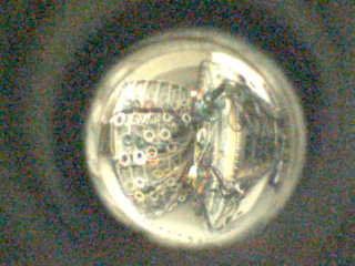
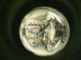
Cover the lens of your sub-$20 fisheye camera with an opaque material and capture some images. The autoexposure system in the camera will use as long a sensor integration time (i.e., exposure time) as possible, also increasing the gain on the analog pixel readout amplifiers to their maximum setting. The result isn't the solid black image you'd expect, but a grayish image speckled with bright colors. What you're looking at isn't really primarily noise, but variations in the fabrication of the pixels on the sensor chip. The cool thing is that this pattern is very consistent from image to image, even over periods of days or weeks. Figure 17 shows two dark noise images captured using the same camera. The dark frames differ even less from an averaged dark frame, which you can easily produce using IMAGEMAGICK's convert program:
Most digital cameras have ``dark noise'' issues, but for higher-quality sensors the noise pattern is more dynamic... it changes mostly in response to changes in temperature, etc. For our cheap little camera, all we have to do to get rid of the noise is a variant of ``dark frame subtraction'' in which we don't have to bother capturing a new dark frame each time but use darkavg.ppm, right? Well, not quite... noise varies with lighting.
In bright light, the images actually have very little noise; as the scene gets darker, noise increases. Ok. So what we need to do is to take the camera's light metering (exposure settings) and use that to weight the correction... except this camera doesn't tell us that information! The answer we use is to compare the image to a dark frame to indirectly determine the exposure, and thus the correction weighting. An image - or a portion of an image - that looks exactly like the dark sensor noise pattern for that area really is dark, and should have the dark noise pattern subtracted at full strength. An image - or a portion of an image - that looks nothing like the dark sensor noise pattern for that area really was captured without significant noise, and thus the dark noise pattern should not be subtracted at all. Of course, it is possible that local image details might happen to look somewhat like the sensor noise pattern, so we use a combination of local and global similarity-to-noise to weight the compensation.
What we are really doing is indirectly making a map of sensor pixel defects and intelligently subtracting them when we see them. Since there is literally no ``blurring'' operation applied, this type of noise removal doesn't compromise image detail, but the reduction in noise is very significant. An example, a side view of our KASY0 cluster supercomputer taken in subdued lab lighting, is shown in Figure 18; the left view is the raw camera image, right is the cleaned image.
It should be noted that for the highest quality this noise reduction should be applied to the digitized sensor data before Bayer color filter interpolation and gamma correction, but Figures 17 and 18 were created by applying noise reduction after using the standard processing applied by GPHOTO2. Thus, the noise reduction can be effectively applied as a postpass, without modifying GPHOTO2 or V4L2, and might even work for other cameras. Software we have created to perform this noise reduction will be freely available from our WWW site, http://aggregate.org/.
If you haven't used a fisheye lens before, it will probably come as a bit of a surprise that the area outside of the image circle isn't a featureless void, but usually contains various lens flare and related artifacts. Combining these defects with the usually not-quite-centered image circle yields images with little aesthetic appeal. In fact, even after removing image noise as described above, the images look ugly. Masking helps a lot.
Image masking is straightforward, although it does involve multiple steps. Here's a simple procedure for making a mask using GIMP:
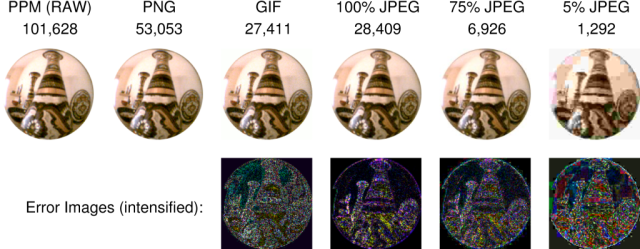
One final note about circular masking: JPEG output doesn't always look good for circular-masked images. JPEG compression uses a frequency-domain analysis - DCT - applied on 8x8 pixel blocks. Thus, a sharp-edge transition within a block, such as will commonly happen at the edge of the image circle, has high-frequency components that will be removed by the normal compression process. We've all seen the inevitable result: patterned noise artifacts within blocks that originally contained sharp edges. Color also is diluted within edge blocks by the white surround. Additional problems can occur if the image dimensions are not a multiple of 8x8.
Any image format that does not use lossy frequency-domain compression will be free of most annoying artifacts associated with JPEGs. The PPM (``RAW'' binary) files created by GPHOTO2 and XAWTV are a convenient uncompressed format to work with, but many WWW browsers don't know how to display them. PNG is losslessly compressed and understood by most WWW browsers. GIF doesn't have edge artifacts, but it uses lossy compression that restricts the image to only 256 different colors.
Which image file format should you use for circular-masked images? Figure 19 shows a sample 184-pixel diameter image encoded in various file formats; for each, the file size (in bytes) and an error image (intensified to make the problems more visible) is given. As the figure shows, the perceptually-based JPEG compression looks acceptably good even at 75% quality - but the errors are not small and edge problems would be significant if the image was further processed. In summary, PNG is best as both an archival and WWW format, but both GIF and high-quality JPEG are acceptable for WWW viewing. For a camera that directly produces JPEGs, such as the DCS-900, you already have suffered JPEG artifacts within the image circle, but you will get compounding of the artifacts if the original and final 8x8 blocks do not line up.
For some applications, it is desirable to convert the circular fisheye image into a rectilinear projection (or any other projection, for that matter). Such conversion can be done fairly well using free software, such as Helmut Dersch's PANORAMA TOOLS (PANOTOOLS), to process the cleaned circular images that result from our image processing pipeline. These excellent, free, tools provide not only high-quality conversion to rectilinear projections, but also cylindrical projections and even 360 degree stitched panoramas rendered in any of various ``virtual tour'' formats. There have been legal issues involving a patent on fisheye projection conversion, the primary impact of which has been that Dersch's incredibly detailed and scholarly WWW site discussing all the techniques and algorithms was removed, although many mirrors of it still exist. A nice set of links and other information about various alternatives appears at www.panoguide.com; the dominant free software seems to be PANOTOOLS, NONA, and the HUGIN front-end (hugin.sourceforge.net).
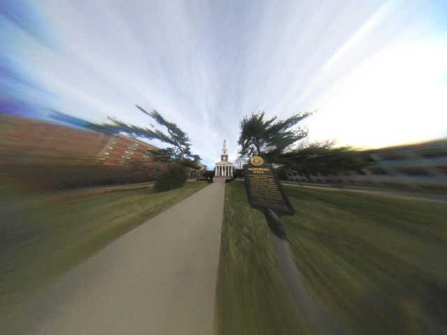
As a simple example conversion, Figure 20 shows an approximately 170 degree rectilinear version of the circular fisheye image shown in Figure 4. This conversion was done by straightforwardly using HUGIN to remap the fisheye projection. A somewhat better image could have been obtained by tweaking the conversion model parameters, but the blurring toward the edges is a normal consequence of rectilinear projection: as the view angle approaches 180 degree, the edge detail gets stretched to cover infinitely many pixels. The resulting image is undistorted in the sense that straight lines in the original scene are rendered as straight lines, not bent around the image center.
It is worth noting that fisheye transformation tools generally assume that the lens matches a relatively simple parametric lens model. Higher-quality mapping can be done using a calibration-driven, rather than abstract lens model-driven, remapping. Such a calibrated mapping can be implemented by assigning each output pixel a (floating point) coordinate position in the original image from which the data value for that output pixel is interpolated. Given the low pixel count of the images, especially for our sub-$20 system, it really isn't worth the calibration effort for most applications.
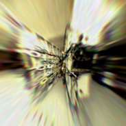
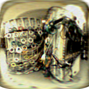
Although a circular fisheye image certainly appears distorted relative to how human eyes see the world, all the other commonly used projections also fail to match human perception of a wide-angle scene. Further, using the peephole fisheye converter, the resolution is arguably low enough that even the minor loss of resolution associated with a projection transformation is not desirable. The three different projections shown in Figure 21 make it clear that resolution with our sub-$20 system is not really high enough for projection transformations to be worthwhile for human viewing. With over half a dozen circular fisheye cameras currently in continuous operation within our labs, we do not routinely convert the projection of any of them.
This technical report details how to combine a $3.20 door peephole viewer with a $14.88 digital camera to produce a sub-$20 digital fisheye camera system with nearly 180 degree angle of view and virtually every distance in focus simultaneously. The camera and lens combination is small and lightweight, making it suitable for a very broad range of applications. Stills and video (without sound) can be captured either independent of a computer or under direct computer control using a USB connection; the necessary software support is freely available as source code and is fully functional under LINUX.
Of course, there are some problems. Although image quality is more than competitive with typical webcams if we do a little careful image processing in software, the camera's low resolution cannot be repaired, and the fisheye image circle doesn't even use most of the pixels the sensor provides. Forget about making high-quality prints much bigger than about one inch in diameter. The sensor's limited dynamic range often is further reduced because the camera's autoexposure logic is fooled by the dark area around the image circle, making it virtually impossible to avoid overexposed highlights in bright, high-contrast, lighting - such as scenes that have a lot of daytime sky in the background. In summary, it is best to think of this sub-$20 system more as a low-resolution imaging sensor for robotics, surveillance, and related tasks than as a general-purpose fisheye camera. For general purpose fisheye photography, using the peephole on digital cameras in the $100 to $150 price range will deliver images as good as the peephole optics allow.
That said, how bad are the images from our sub-$20 system? They are better than you feared and not as good as you hoped. Judge the following images for yourself.
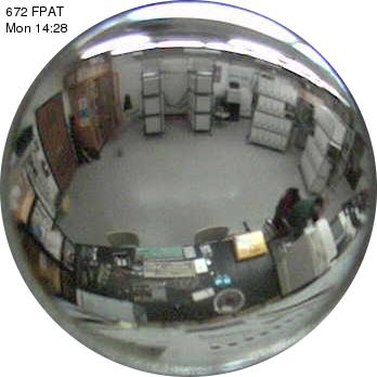
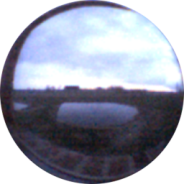
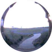
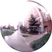
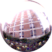
As stated earlier, blown highlights are inevitable using this camera in bright, high-contrast, lighting. Figure 22 gives five examples. The first is a view from a second-floor window (the frame of which is mostly visible) looking toward a half-acre pond and a large black barn across an empty field. The sky is not entirely washed-out, but the majority of the usable exposure range went to representing the sky's texture, leaving the ground very dark; looking straight up at a cloudy sky often results in a very similar rendering of the cloud texture. The second image is the scene taken looking out a front door, showing a concrete walkway and a blacktop circular driveway. It is a more typical rendering of an outdoor scene with both ground and sky taking significant portions of the image area; the entire sky is washed out but the remainder of the scene still has good detail. The same general effect is seen in the remaining three photos, which were taken around the F. Paul Anderson Tower at the University of Kentucky.
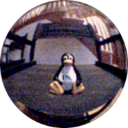
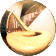
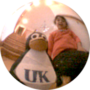
Indoor lighting also can be contrasty, but rarely spans as wide a range as sunlight; the larger problem is that normal home room lighting often is too dim for this type of camera. Figure 23 shows that the camera actually does fairly well on this type of scene, with sensor noise as the biggest problem. The first image is a 3 1/2'' tall penguin sitting a few inches from the lens on a black director's chair with no lighting directly on the chair; even after noise reduction (described in Section 6.1), this scene was just too dimly lit to generate a low-noise image. The center image is the stairway right behind where the penguin was seated; the camera did surprisingly well on this scene, perhaps because room lighting hit most of the scene without the sources being visible (i.e., a relatively low contrast scene). The third image is taken on a different portion of the stairway - the five-year-old girl is really quite a bit larger than that penguin. Despite blowing-out the light sources, the image isn't bad. In summary, low light isn't so bad for this camera provided that the noise reduction discussed in Section 6.1 is applied.
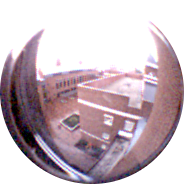
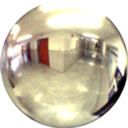
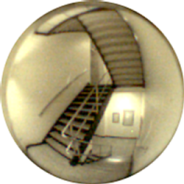
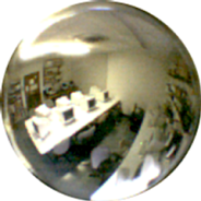
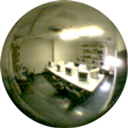
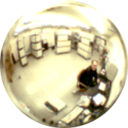
A likely application of this sub-$20 fisheye camera is as a surveillance sensor. While resolution is not sufficient to identify specific individuals unless they come fairly close to the camera, typical lighting in public spaces and commercial buildings usually is suitable for the camera to capture relatively good quality images. Figure 24 shows surveillance-style photos of a hallway, stairwell, the Open Computing Laboratory (OCL), and the machine room that houses the KASY0 supercomputer - all in F. Paul Anderson Tower at the University of Kentucky. The ambient lighting of the hallway and stairwell both were typical of such spaces. The OCL was unoccupied at the time, so its lighting was subdued by commercial standards, but still fairly bright compared to home lighting. Incidentally, in the two photos of the OCL, the tables have bright white plastic tops, so it is not surprising to see that highlight detail in them is minimal. The machine room had all lights on (and directly visible at the top of the image). All five images are of good quality, with the stairwell image being somewhat better than the others because it does not have the light sources directly in the field of view. Overall, the system works well for surveillance applications, often best when ceiling-mounted and pointing downward - because room lights are usually ceiling mounted, pointing the camera downward tends to yield the most even lighting while keeping the light sources out of the image or near the image edges.
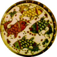
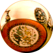
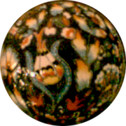
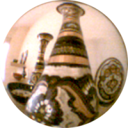
Brighter artificial lighting, more typical of office lighting, still tends to have relatively low contrast, but doesn't have the sometimes severe noise problems associated with dimmer lighting. Again, keeping the light sources out of the frame significantly improves the image quality. The images in Figure 25 look about as good as our sub-$20 fisheye digital camera can produce. All five of these photographs are extreme close-up shots of various Turkish ceramics and metalwork, with the lens within an inch or two of the nearest object in each image. For example, the cups in the fourth image are less than 1 1/4'' tall.
It should be noted that color balance for all the indoor photographs is tricky because common light sources have widely varying spectral properties. In particular, the pink casts in Figure 25 are probably not really indicative of a flaw in the camera's color rendition, but the natural consequence of the spectrum of the halogen lighting used. The same issue occurs in Figures 18 and 21 with respect to a blue-green tint caused by fluorescent lighting.
Although the work presented in this technical report was not externally funded per se, it is in large part a spin-off from externally funded research work involving use of digital cameras for 3D capture. The author is honored to hold the James F. Hardymon Chaired Professorship in the University of Kentucky's Department of Electrical and Computer Engineering, and it was with endowment funds that much of hardware discussed here was purchased (not just the peepholes and SAKAR cameras, but also the D-LINK DCS-900, CANON Powershot S70, and SONY DSC-F828 cameras).
The work freely presented in this technical report is in no way warranted to be correct, or suitable for any particular application, by the author or by the University of Kentucky. Use of this information is entirely at your own risk. However, the author welcomes comments and corrections, and intends to update the report as time permits.
Because the commodity parts used in building the sub-$20 fisheye camera discussed in this technical report are used in ways not originally intended by the manufacturers, normally insignificant differences between similar products can be important. For this reason, we have made an effort to identify the specific models used. The fact that a particular model is referenced in this document does not imply that either the author or the University of Kentucky endorse that product or its vendor. Opinions expressed in this document might be those of the author, but certainly are not an official position of the University of Kentucky.
![]() The only thing set in stone is our name.
The only thing set in stone is our name.