
Trace2SCAD: Converting Images Into OpenSCAD Models
H. G. Dietz
http://aggregate.org/hankd/
Department of Electrical and Computer Engineering
Center for Visualization & Virtual Environments
University of Kentucky, Lexington, KY 40506-0046
Initial release: January 4, 2015; last update: September 19, 2015
This document should be cited using something like the bibtex entry:
@techreport{trace2scad20150104,
author={Henry Gordon Dietz},
title={{Trace2SCAD: Converting Images Into OpenSCAD Models}},
month={January},
year={2015},
institution={University of Kentucky},
howpublished={Aggregate.Org online technical report},
URL={http://aggregate.org/MAKE/TRACE2SCAD/}
}
Anyone who has ever played with a 3D printer no doubt almost
immediately encountered the little problem of having a 2D image
that they wanted to convert into a 3D model. However, there's a
special reason this became a priority for me now: for the first
time in over three decades of being a professor, in Fall 2015, I
will have a blind student in one of the classes I teach. My
course unfortunately has significant visual components in the
form of various diagrams, so one of the obvious possible
approaches would be to try to use my 3D printer to create
tactile versions of the key graphics for the course. I created
trace2scad to facilitate making these "bump readable"
graphic images using my MakerGear M2 3D printer.
Trace2SCAD is distributed as full source
code under Creative Commons - Attribution constraints. You
use it at your own risk, with no warranty, etc.
Background
There are many ways to convert 2D graphics into a 3D-printable
model. There are even a number of free software tools
explicitly supporting this type of transformation. To name a
few:
-
PNG23D is a
very widely available free tool that converts a PNG image into
either an OpenSCAD or STL file. It's not fast, but directly
generates a triangle mesh for a manifold polygon representing
the pixel values as heights. Put another way, this converts an
image into a Lithophane, and can even deal with color.
-
Img2SCAD is a
Python tool that converts a monochrome image into an OpenSCAD
structure that is essentially a cube per pixel, such that the
cube height represents the "whiteness" of the corresponding
pixel.
-
OpenSCAD itself has long included a surface()
primitive that can read a raw data file and represent it an an
object where the height at each point corresponds to the data
value for that point, with nicely sloped transitions between
points. The data file format is not an image per se, but
consists of ASCII text giving whitespace-separated integer pixel
heights -- which is easily generated by stripping the header off
an ASCII PGM file (the type that begins with the sequence
P2). As of the 2014.QX versions, there is also provision
for reading-in a PNG image, with gray scale values computed
as Y = 0.2126R + 0.7152G + 0.0722B and scaled to 0..100.
-
Inkscape offers a very
different alternative. It is capable of directly manipulating
vector drawings and can even trace pixel-based images to create
vector forms. These vetor forms can then be saved as DXF files,
which tools like OpenSCAD can import directly. The catch is that
the vector model in Inkscape is far more general than what DXF
files can represent, so the drawing must be processed to remove
constructs like smooth curves, replacing them all with
straight-line segments. In the "Extensions" menu, there is an
option called "Flatten Beziers" which does this simplification
with a user-settable "Flatness," but it is notoriously
unreliable. It is worth noting that the output of Inkscape is
completely flat in the sense that model height is fixed at 1
unit.
-
Image to lithophane
is a fantastic WWW-based tool for creating 3D STL meshes from
images. It's probably what you want if you want to make
lithophanes. However, it generates models with complexity
proportional to image pixel count.
-
Cura
now has the ability to read-in an image file and create a smoothed
height-map, which it can "save model" as an STL file. It's not
particularly clever, but it's free, fast, and really easy to use.
Model complexity is proportional to pixel count.
Can be used to make simple lithophanes.
-
Selva3D is yet another
WWW-based tool for generating 3D models from 2D images. It
charges for "high quality" STLs, but delivers lower-quality ones
for free after a 2-minute delay. It seems to be attempting to
simplify the model much as trace2scad does, but perhaps
not as successfully. Still, it does appear to generate 3D output
directly.
Given all those different approaches (and there are many others
not mentioned above), why are we creating and posting yet
another tool to convert images into models? Well, we generate an
OpenSCAD model, not an STL file. In addition, OpenSCAD
doesn't deal well with very complex models, so we try to
moderate model complexity. Unfortunately, to get smooth-looking
structures from all the above except Inkscape, you need lots of
pixels and model complexity for most of the above is directly
proportional to the total number of pixels in the image.
Inkscape solves this problem, but not in an easy to use nor
reliable way. Trace2SCAD is doing much the same processing as we
would do with Inkscape, but it is much faster, easier to use,
directly generates an OpenSCAD model of controllable size, and
hopefully will prove to be more reliable.
One more thing: trace2scad also knows how to build
multi-layer models somewhat like the pixel bump maps built by
other tools, but not based on pixels. The 3D models
are presented as a set of discrete layers, so it would be more
technically correct to call it 2.5D rather than 3D.
How Trace2SCAD Works
Trace2SCAD is a shell script using sed, awk,
ImageMagick convert, mkbitmap, and
potrace. Thanks to convert, nearly any image
file format can be used for the input, and mkbitmap is
used to further enhance the image for procesing, but the bulk of
the work is really done by the incredibly useful Potrace. That tool
is also what does the heavy lifting for Inkscape. However,
rather than letting potrace go to all the work of
generating smooth curves and then converting them to
straight-line segments, we simply tell potrace to
output straight-line segments. The specific style of grouped SVG
output by potrace is then parsed and reprocessed to
create an OpenSCAD module definition.
There are a few options that we'll discuss in the following
section, but there is one that is particularly important and
unique to this tool: trace2scad allows you to specify a
maximum model complexity, and will automatically iterate
simplifying the image and retracing until a model is created
that does not exceed the target complexity. Thus, you have
direct control over the compexity of the OpenSCAD model -- which
is critical given that OpenSCAD can take many hours to render
overly complex models, often quietly failing after many hours of
processing.
Using Trace2SCAD
Trace2SCAD is really very easy to use, essentially able to
accept just about any type of 2D image file as input and
directly generating an output file that contains the OpenSCAD
model as a set of module definitions. The modules are always
scaled to be bounded within a 1mm cube that is sitting on the
Z=0 plane and is centered at X=0, Y=0. That is almost certainly
too small to be used directly; for example, if
lithophane() is the name of a generated module that you
want to make have a maximum X or Y dimension of 100mm and Z 3mm,
this can be done using scale([100, 100, 3])
lithophane();. Note that the X/Y aspect ratio of the
original image is preserved by trace2scad, so the X and
Y scaling components should normally be the same value.
At this writing, the command line for trace2scad has
fair number of options, but most are rarely needed. The basic
usage is:
trace2scad {options} inputimagefile
The command line options are:
- -a
-
Force alignment of the model based on image bounds (also
--align). Normally, the model is centered based on the
bounding box computed from the generated models, but that means
position of the object within the original image is lost. Thus,
overlaying multiple trace2scad models from the same
original image will not align them. To ensure alignment,
-a is automatically set if you are generating models
for more than one layer.
- -c number
-
Set the target model complexity (also --complex). The
model will be iteratively simplified until the total number of
points in the polygons is no more than number.
- -e number
-
Set the maximum line-combining error in pixels (also
--pixerr). When the model is converted to line
segments, very often there will be cases where a sequence of
multiple line segments could be converted into a single line
segment with minimal error. This option sets the maximum
distance, in pixels, that a discarded point can be from the line
that replaces it. The default value is a very conservative 1.0;
larger values will tend to greatly simplify the model while
"smoothing" minor bumps that often happen due to pixel-level
aliasing of the original image. For high-resolution images,
-e 2 to -e 10 can really help smooth things
with minimal ill effect. This feature was added in version
20150415.
- -f number
-
Set the highpass filter radius (also --filter). If set
to 0, the image will simply be thresholded to find edges and
large dark areas will be modeled as solids. If set greater than
0, the effect is to convert constant-brightness regions into
outlines with an edge thickness proportional to the
number. Generally, a value between 2 and 4 is
appropriate for outlining.
- -g number
-
Set the image gamma (also --gamma). This allows simple
adjustment of the tonal spread of the image before filtering
and thresholding.
- -h
-
Print the command line help message to stderr and exit.
- -l levelspec
-
Set the level threshold or thresholds (also --level).
A level directly determines the cut-off between model and void.
The number should be a decimal value between 0 and 1
(exclusive); for example, "-l 0.5" would set a single
threshold of 0.5. However, this command line option can also be
used to specify multiple levels to create a contoured 3D model
by union. Such a 3D contour, for example, can be used as the
model for a Lithophane. You can give a single integer value (with no
".") to request creation of that many levels with level
thresholds equally spaced between 0 and 1. For example, "-l
4" would create four levels. If you want direct control
over the individual levels used, you can instead list them with
"," between the threshold values: "-l
0.875,0.625,0.375,0.125" produces the same result as
"-l 4" -- creating four levels. If more than one level
is specified, -a is implied to ensure that the levels
will align correctly.
- -o file
-
Set the file name for the OpenSCAD output to file.
Normally, the output file name is derived from the input
filename by replacing any characters after "." with
".scad" -- but that can be a problem if the image is
coming from a read-only directory, etc. When you specify a
different name using -o, the name is used precisely as
entered, without adding the suffix ".scad."
- -p prefix
-
Set the name prefix to use for the generated OpenSCAD model
(also --prefix). By default, the name prefix is derived
from the image file name by removing the portion of the name
after ., but that might not result in an appropriate
name. For example, files can have - in their names, but
OpenSCAD modules can't. The resulting model can be instantiated
by prefix();; an individual layer of the model
can be instantiated by
prefix_number(); where
number is the level number starting at 1.
- -s number
-
Set the sub-pixel resolution (also --subres). This is
really a potrace parameter, determining the fraction of
a pixel to which analysis is performed. Larger values are more
precise, but values between 2 and 10 generally suffice.
- -t number
-
Set the "turd" size (also --turd). This is really a
potrace parameter, and the name isn't my fault. Any
traced region smaller than number pixels is essentially
discarded from the model.
- -v
-
Enable verbose output to stderr (also --verbose).
There are some other messages that go to stdout, but these can
be isolated because they go to stderr. Enabling verbosity also
has the side effect of leaving temporary files holding the
intermediate stages in processing, so it would be appropriate to
think of it as primarily a debugging option.
- -x number
-
Set the maximum X axis pixel resolution of the image (also
--xres). This value doesn't have as straightforward an
effect on the model as one might expect, but larger values tend
to create somewhat more complex models. The iterative complexity
scaling is actually implemented by reducing this value and
reprocessing.
- -y number
-
Set the maximum Y axis pixel resolution of the image (also
--yres). Just like X, but for the Y axis....
- inputimagefile
-
The inputimagefile can be in any format understood by
ImageMagick convert. The portion of the name after .
is stripped to create the default prefix for OpenSCAD model component
names. The output file name is also generated from inputimagefile
by removing the portion of the name after . and replacing it with
.scad. For example, test.jpg would produce OpenSCAD
code names starting with test and would place the output in a
file named test.scad.
Examples
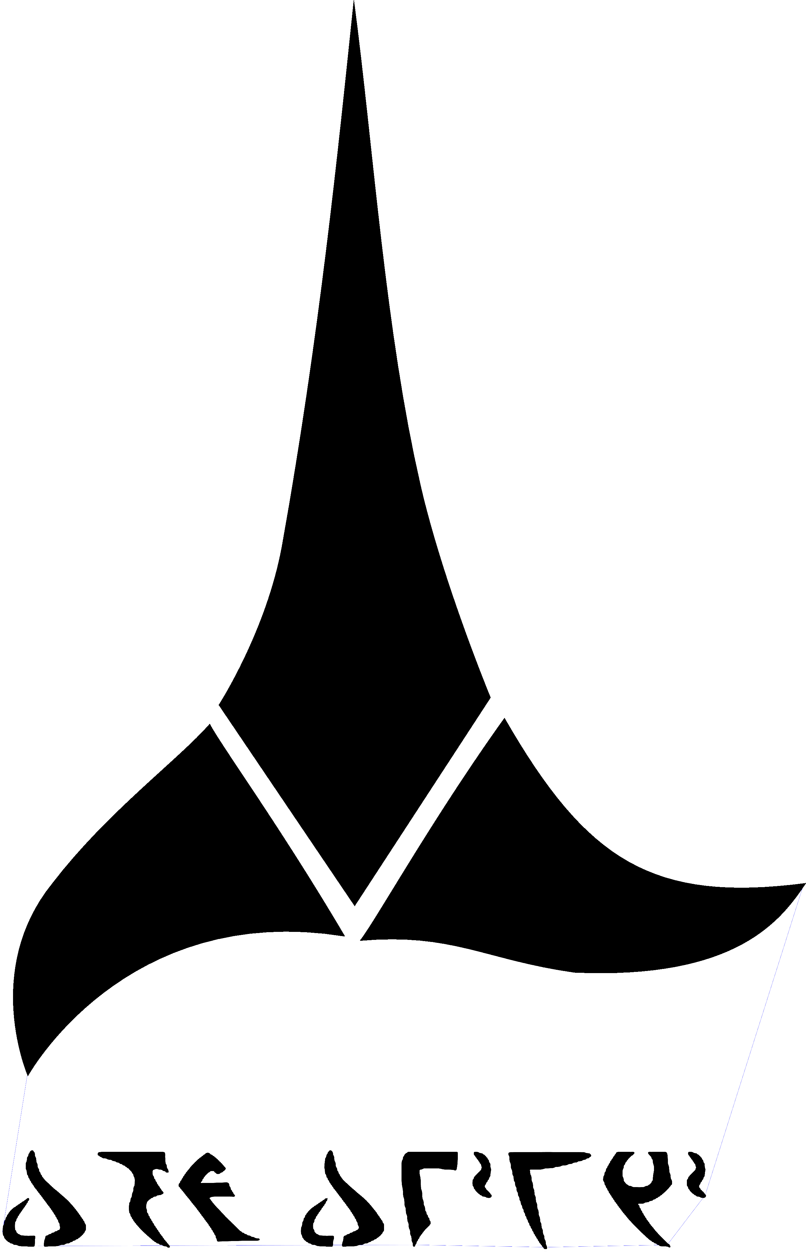
Let's start with an easy one: converting a Klingon plaque design
for my parallel processing lab into an OpenSCAD model. The
command line was:
./trace2scad -f 0 klingon_dondewi.png
The generated OpenSCAD model
file is fairly straightforward, and the model is simply
klingon_dondewi(). The -f 0 said to keep
solid areas solid. We could also have let the system do highpass
filtering to extract edges:
./trace2scad -o fd.scad klingon_dondewi.png
The generated OpenSCAD model file is
fairly straightforward, and the model is again simply
klingon_dondewi(). The original input image and the
two OpenSCAD 3D models (scaled to 200x200x1) look like:
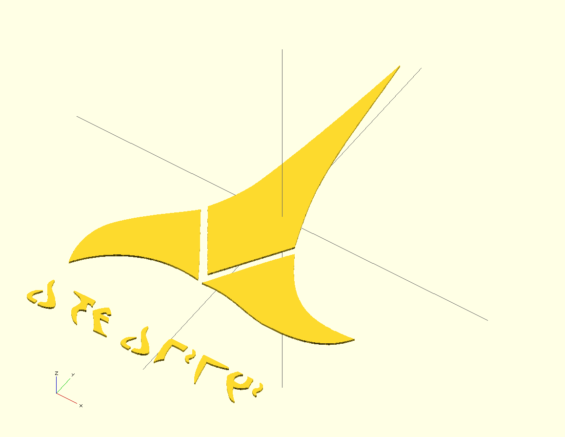
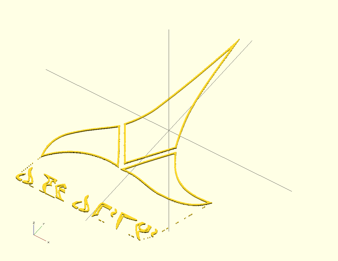
Ok. That was easy. The second model seems to have done a good
job of extracting the outlines, except there's also some fluff
that doesn't belong. You can easily fix them using the
-t option to remove those little "turds" (as
potrace calls them). Actually, had I not been so
sloppy when making the image, there wouldn't have been a weak
broken edge there for trace2scad to detect in the first
place....
As of version 20150415, the -e option can really help
to smooth-out the model. This OpenSCAD model, generated by ./trace2scad -f 0 -e
10 klingon_dondewi.png, is much cleaner and simpler than
the ones above. It uses just 387 points, which is only about
1/10 as many as the above models, yet the quality of the model
is not clearly inferior; in some ways, it is actually better.
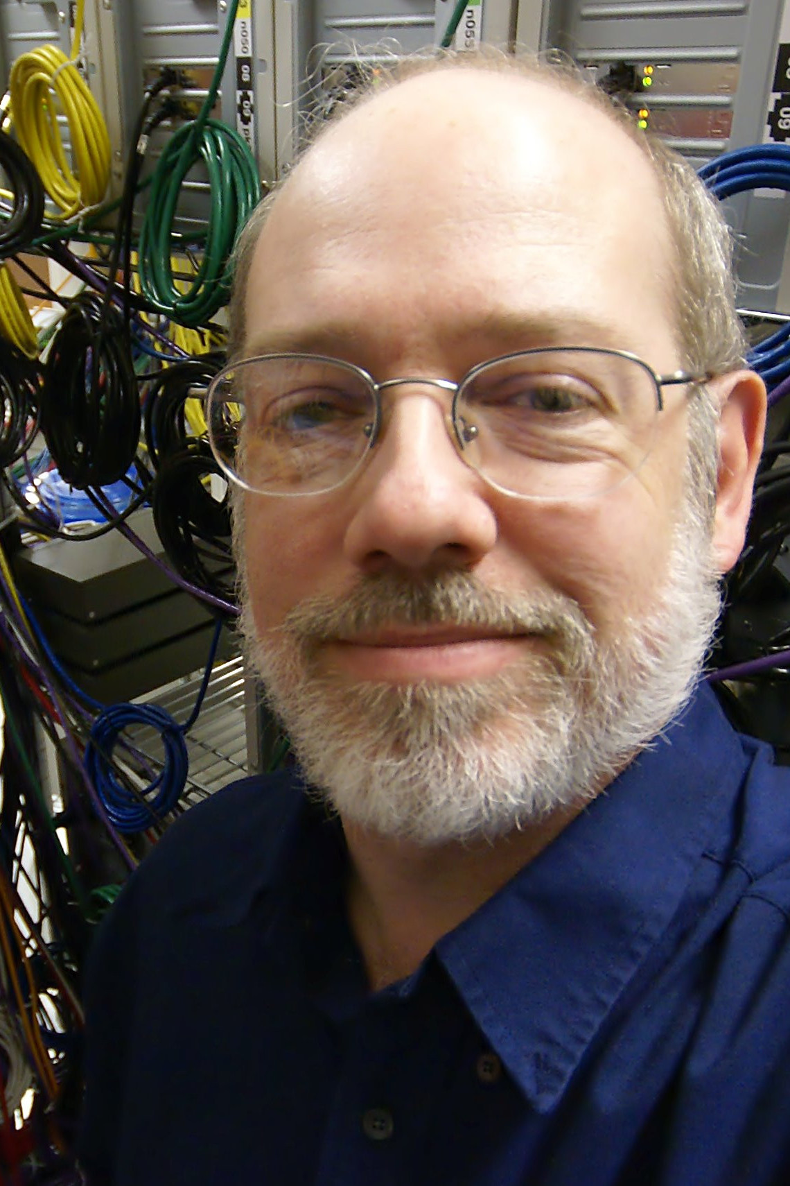
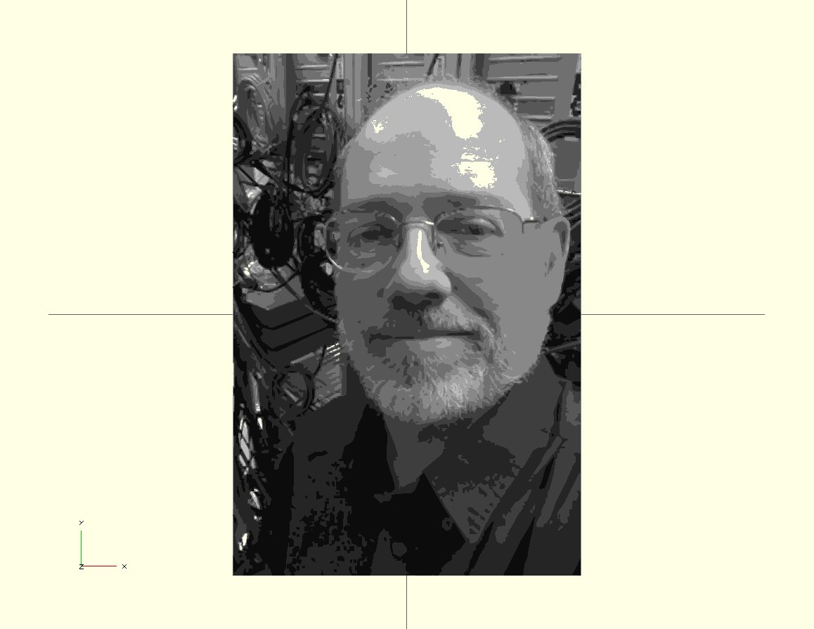
Here's a harder case: my face. For this one, we'll ask
trace2scad to make an 8-layer lithophane:
./trace2scad -f 0 -l 8 testface.jpg
This OpenSCAD model is the result
of converting the following image into the design shown by OpenSCAD.
Yes, by default trace2scad sets the object colors based on
the threshold used for each level, so it really does look like a
monochrome image.
The Source Code
It's just one file -- a shell script. The
latest version is trace2scad.
All released versions of trace2scad are linked here:
- trace2scad20150106
-
Initial release. Probably buggy? Let me know if you find
anything....
- trace2scad20150107
-
Quick clean-up of the initial version. Potrace often generates
line segments that are segments of a potentially longer line
segment, so this version optimizes those out, and now also
prunes the too-complex trace attempts faster.
- trace2scad20150415
-
Added the -e option to dramatically reduce model
complexity and smooth bumps due to pixel-level aliasing.
Minor other tweaks.
 The only thing set in stone is our name.