

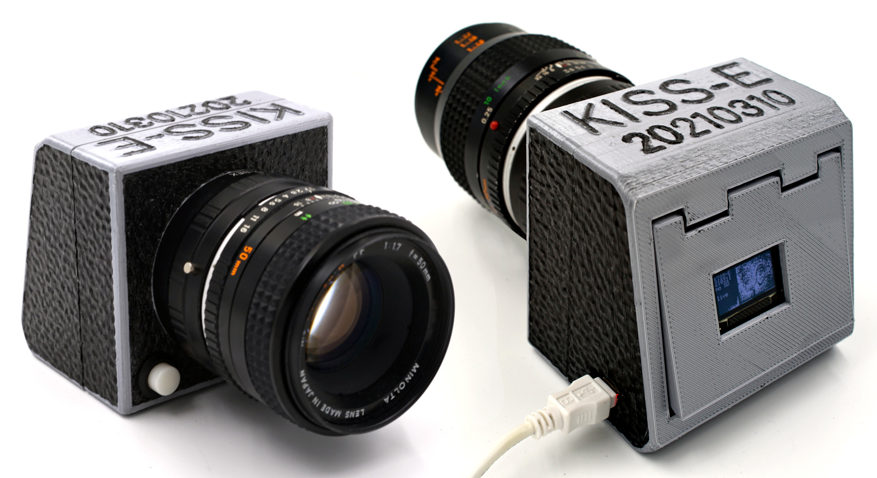
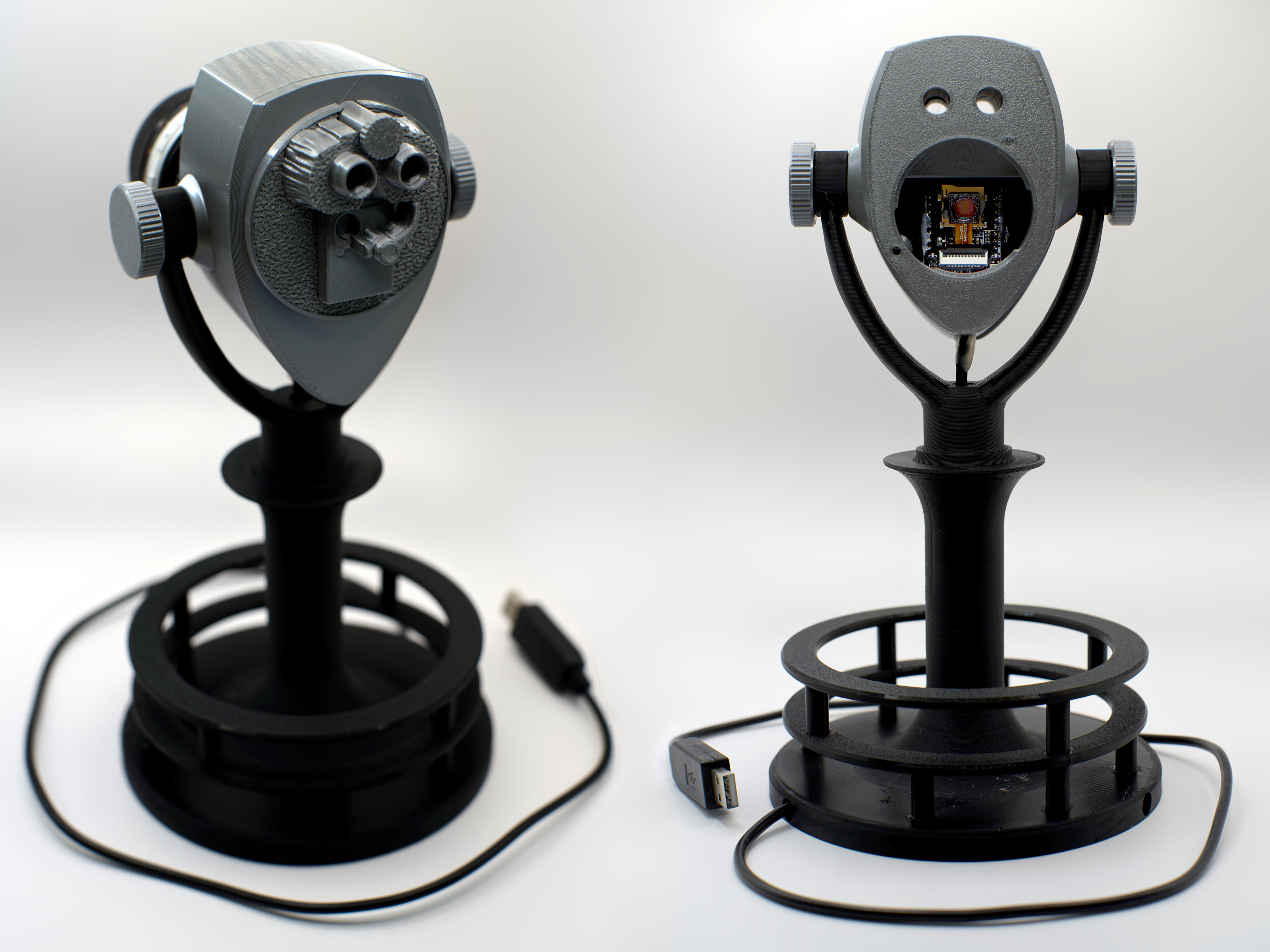
Front and back views of KISS-E and KISS Viewer
This document should be cited using something like the bibtex entry:
@techreport{KISS,
author={Henry Gordon Dietz},
title={KISS: Kentucky's Interchangeable lens Small Sensor cameras},
month={September},
year={2026},
institution={University of Kentucky},
howpublished={Aggregate.Org online technical report},
URL={http://aggregate.org/DIT/KISS/}
}
Latest revision is September 18, 2026.
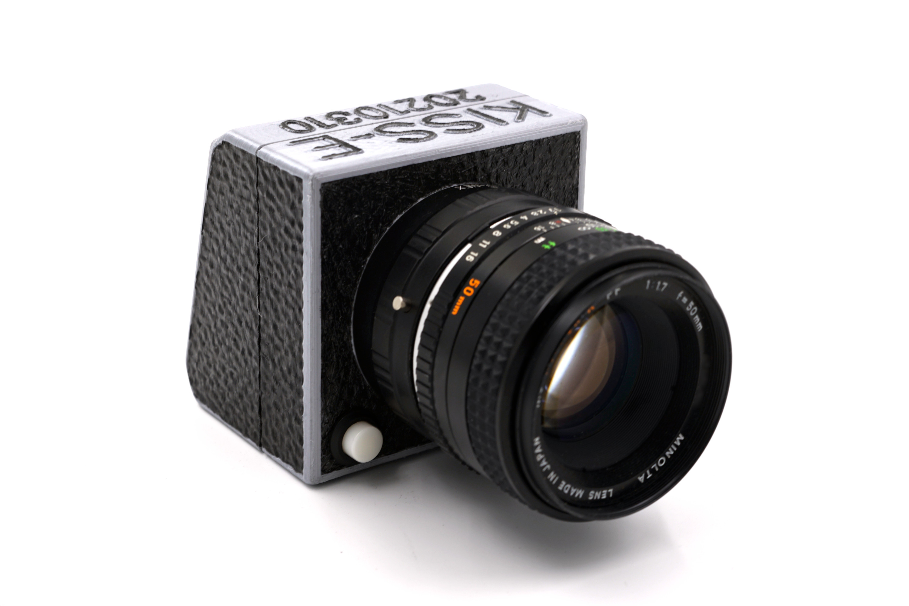
The KISS project began in 2021 with the creation of the original KISS-E. The goal was for KISS-E to be a very inexpensive interchangeable-lens camera able to use any manual lenses adaptable to Sony E/FE mount. It does this by re-packaging the guts of an ESP32-CAM as a fully stand-alone mirrorless camera that can also be remote operated via a web page interface the camera hosts over 2.4GHz 802.11 WiFi. The transformation of the ESP32-CAM into KISS-E required both hardware and software, which were fully operational in January 2022.
The catch is that the original KISS-E was really awkward to use as a stand-alone device. The problem is primarily that the tiny sensor in the ESP32-CAM's OV2640 camera results in a crop of 9.7X relative to full-frame 135 film most adapted lenses were designed for. That makes lenses rather extreme telephotos, and thus fandamentally incompatible with a hand-held stand-alone camera without image stabilization and suffering a very slow rolling electronic shutter.
Then, on August 18, 2026, DPReview published the article: The 90-year history of the binoculars bolted to scenic overlooks. I remember seeing Tower Optical viewers on the Empire State Building's observation deck, at Niagara Falls, and so many other places throughout the USA. Honestly, my fondest memories of them are not about looking through them, but about the excitement of seeing the viewers themselves. Put simply, what Michelin stars are for restaurants, these viewers are for scenic overlooks. Seeing them means that I, and my cameras, have arrived at one of the country's most spectacular scenic overlooks.
However, when I read the DPReview article, I realized that the general shape of these viewers isn't just highly nostalgic, but is actually one of the most functional ways to mount an imaging system delivering an extreme telephoto view. In sum, I realized that this should be the new shape of KISS. And so KISS Viewer was born. KISS Viewer is not a clone of a Tower Optical Viewer, after all, it's less than a foot tall. However, it benefits from the simple tilting mount and allows the viewing holes to be used for quick approximate targeting of the camera. It's also not fully stand alone, but takes advantage of a smartphone or computer to control the camera via 2.4GHz 802.11 WiFi -- which is great, because adjustments to controls made via WiFi don't cause camera vibration.
The remainder of this page explains how to build and use both types of KISS camera. KISS Viewer is listed first because it is a newer and much more practical camera, then the original KISS is described. After that, I have posted information about postkiss, custom postprocessing software to maximize the quality of images captured using either KISS camera. Of course, in keeping with the Aggregate.Org tradition, everything about KISS is open source: both hardware and software.
However, before that, it is useful to say a bit about the choice of the 2MP Omnivision OV2640. The linked datasheet is cached locally because this is an ancient part: the datasheet is dated February 28, 2006. The key thing to note is that the sensor's image area is 3590x2684um. That makes each of the pixels roughly 2.24um square, which is actually pretty big by current small-sensor standards. Alternatively, the ESP32-CAM can use a OV3660, which does provide 50% more pixels, but those pixels are just 1.4um for a total image area of 2912x2167um -- significantly smaller than the OV2640. If you can deal with violating the operating voltage specification when using the ESP32-CAM interface, the OV5640 offers 5MP. Unfortunately, it also uses 1.4um pixel pitch, so the image area is 3674x2738um -- nearly the same size as the OV2640. If you switch to a different microcontroller, there are more higher-resolution options, but most use sensors that aren't bigger than an OV2640. In sum, nearly all lenses you can adapt aren't out-resolving 2.25um pixels, so the higher-resolution sensors are typically more trouble than they are worth for this type of use. In fact, high-end smartphone sensors now have pixels smaller than 0.6um, and rely on rather exotic, highly tuned, lens designs to get decent resolution. Many, including some OV5640, also incorporate autofocus mechanisms that make removing the native lens problematic.
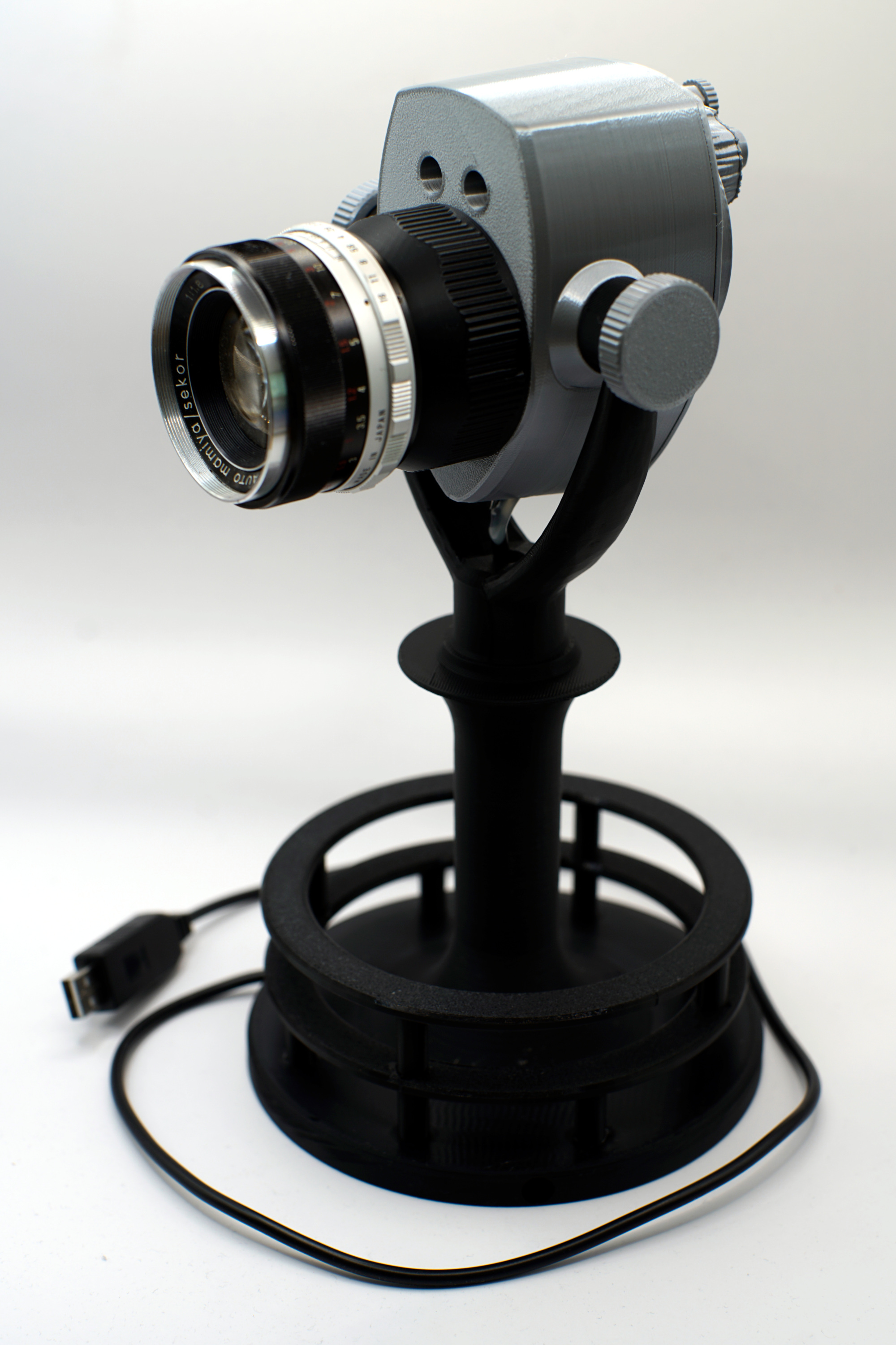 KISS Viewer looks like a 3D-printable model of a Tower Optical
Viewer. It's not. I designed it by first looking at lots of
photos of Tower Optical Viewers, searching for models (there are
some, not free), then asking several AIs to create designs. In
the end, I basically synthesized my own design almost from
scratch in OpenSCAD. My design is much shorter than a scale
model would be and the foot step rings are taller. Except for
the basic shape of the fork and the area around the view holes,
everything has been replaced with my own design elements that
are more appropriate to the task. Still, it reminds you of one
of those viewers, doesn't it? ;-)
KISS Viewer looks like a 3D-printable model of a Tower Optical
Viewer. It's not. I designed it by first looking at lots of
photos of Tower Optical Viewers, searching for models (there are
some, not free), then asking several AIs to create designs. In
the end, I basically synthesized my own design almost from
scratch in OpenSCAD. My design is much shorter than a scale
model would be and the foot step rings are taller. Except for
the basic shape of the fork and the area around the view holes,
everything has been replaced with my own design elements that
are more appropriate to the task. Still, it reminds you of one
of those viewers, doesn't it? ;-)
Aside from nostalgia, this shape is useful because a tilting fork is basically what you need for aiming the lens. The catch is, aiming this is incredibly touchy with some lenses, and for that you can use the viewing holes. There are no optical elements in the viewing holes, and you're not going to be able to look through both holes at once for binocular vision, but either hole acts as a pretty good sight for aiming whatever lens you're using. The real viewers rotate in the middle, but this one is easily rotated as a whole, and that makes it stronger than if the post contained a pivot. Strength and balance are both major concerns here, and this design scores much better on both metrics than a true model of a Tower Optical Viewer would.
All the build info for KISS Viewer is posted as an Instructable: KISS Viewer: Kentucky's Interchangeable-lens Small Sensor camera in a mini Viewer. It is a very easy build although there are a lot of parts to 3D print. The STL models are freely available from KISS Viewer at Printables.Com. Of course, you'll also need firmware for the camera...
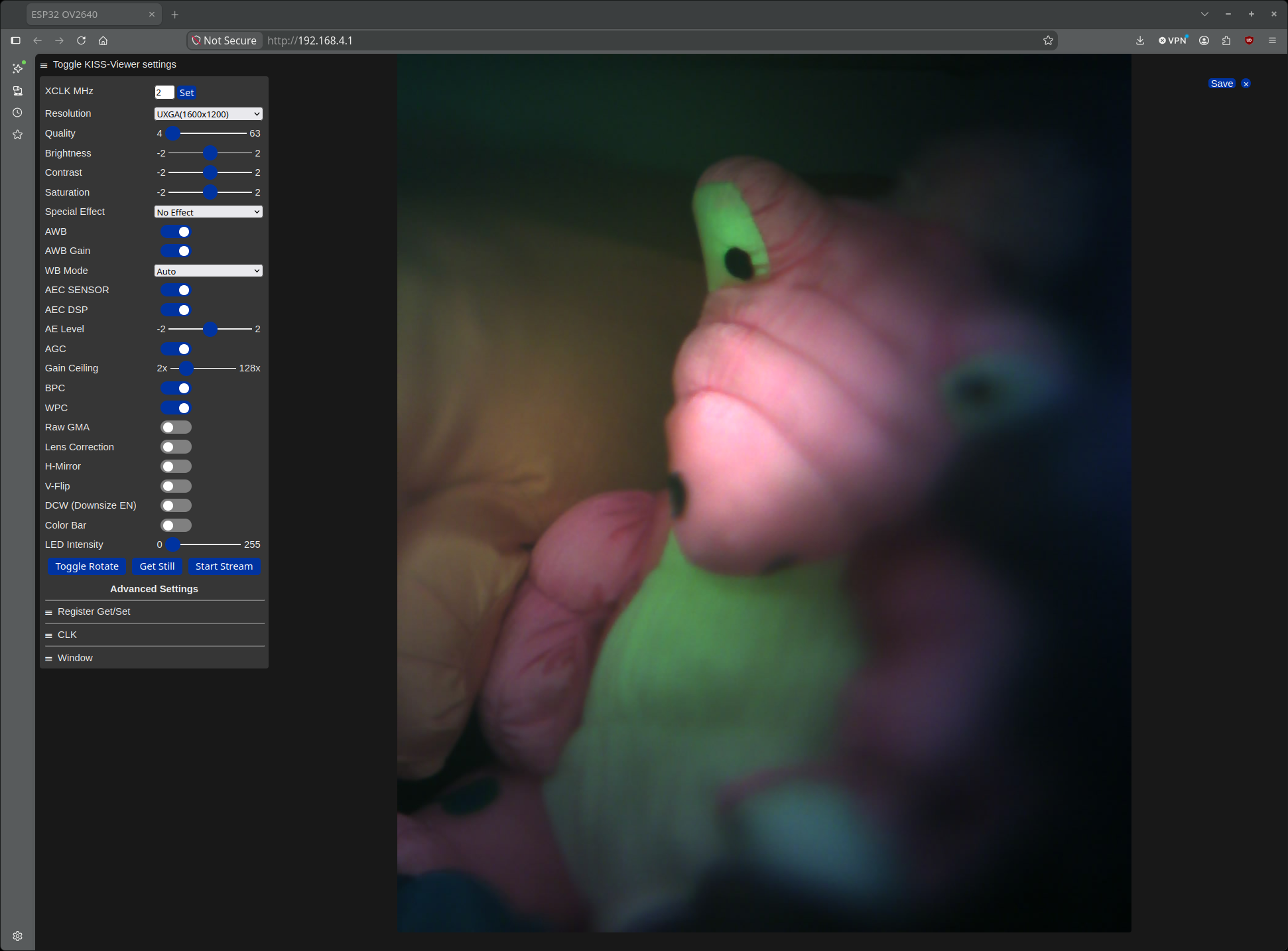
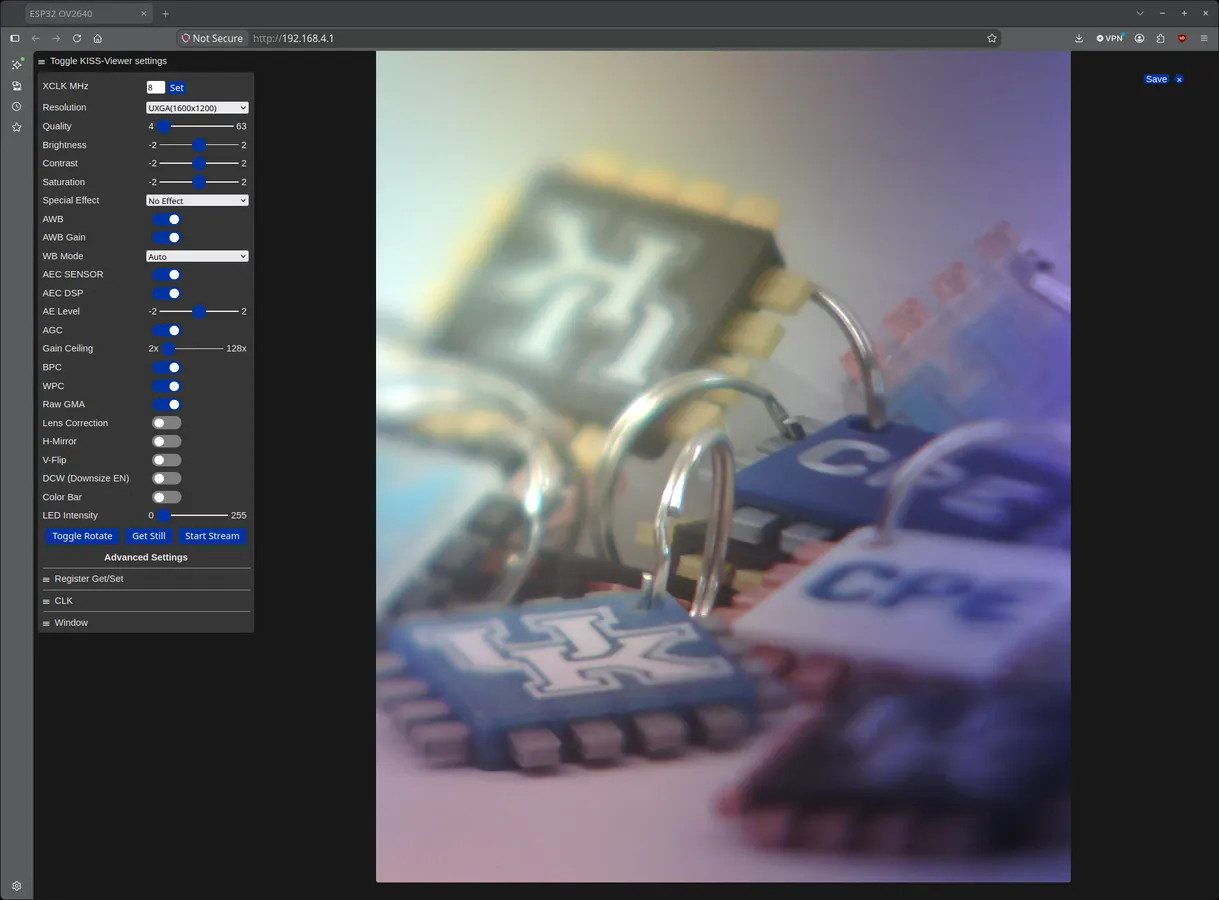
Initially, the page will not have an image displayed; that's enabled by one of the buttons near the bottom of that scary-long menu. You can find more about these options in various places on the WWW, but here we will briefly cover the most significant:
Note that there is no electrical coupling to the E/FE mount or any lens attached. Thus, focus and aperture control are entirely manual. There also is no mechanism for including useful EXIF data in an exposure. In fact, the ESP32-CAM does not have a clock that runs while power is off, so even timestamps are not feasible. On the other hand, saving an image on your computer or smartphone will generally tag the file with a timestamp.
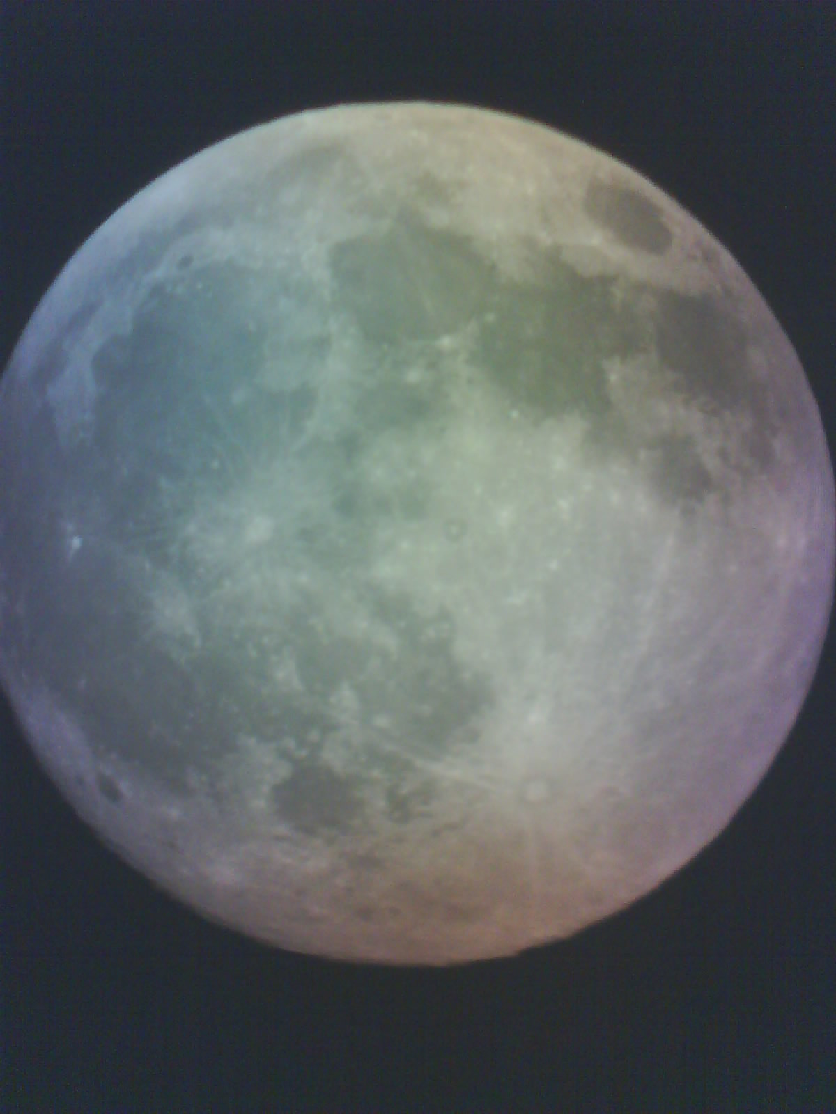
Let's start with some unprocessed captures shot with lenses from 45mm to 300mm:



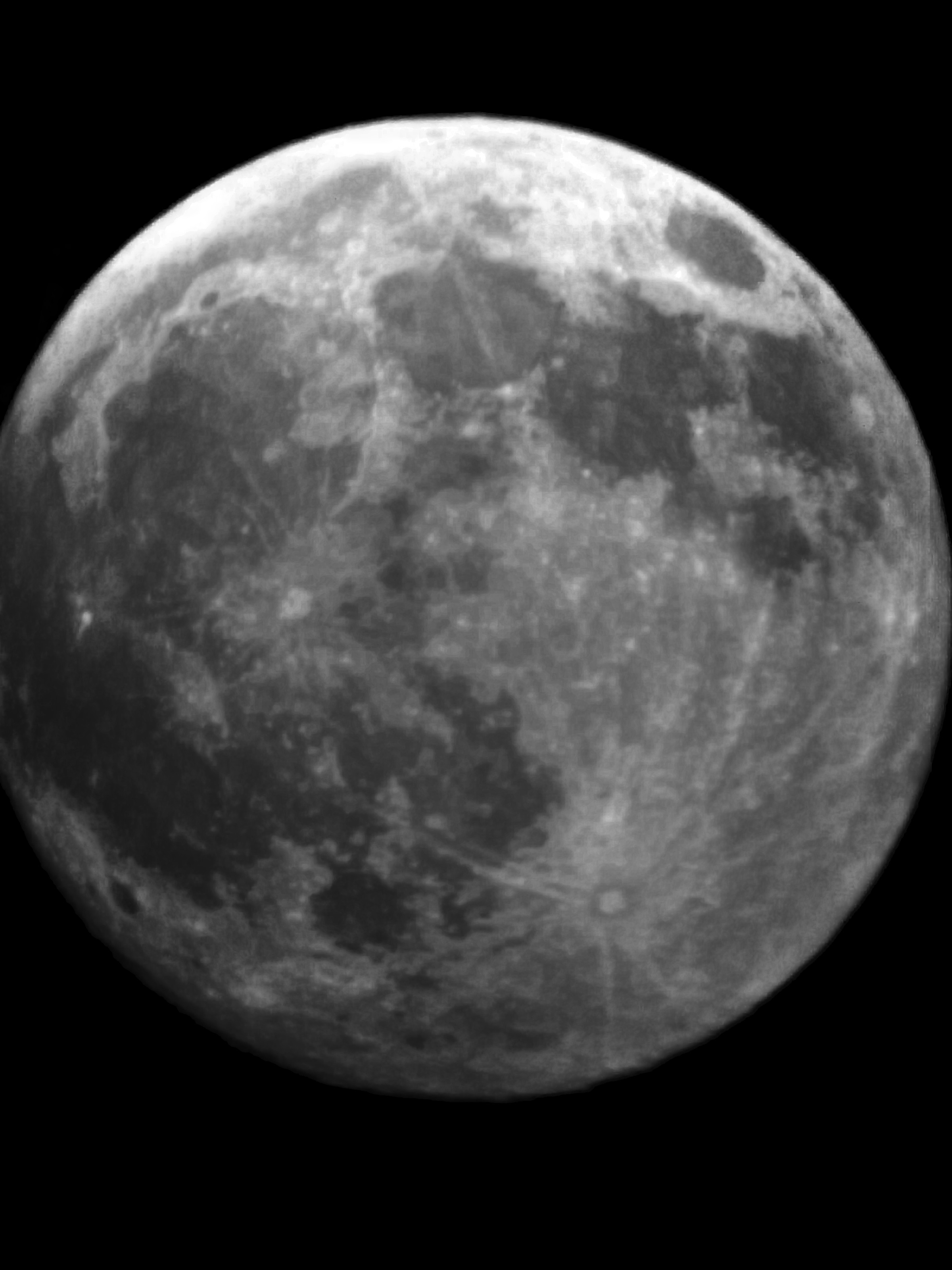
And here are those scenes improved using multiple captures with postkiss postprocessing:



 The KISS project began in 2021 with the creation of KISS-E.
KISS-E is a very inexpensive interchangeable-lens camera able to
use any manual lenses adaptable to Sony E/FE mount. It does
this by re-packaging the guts of an ESP32-CAM as a fully
stand-alone mirrorless camera that can also be remote operated
via a web page interface hosted over 2.4GHz 802.11 WiFi. The
transformation of the ESP32-CAM into KISS-E required both
hardware and software, which were stable by the time we
published on KISS-E as one of the example systems discussed in
our January 2022 Electronic Imaging paper, ESP32-CAM
as a programmable camera research platform, the full text of
which is freely available via that link. The presentation
slides for that paper are also freely available.
The KISS project began in 2021 with the creation of KISS-E.
KISS-E is a very inexpensive interchangeable-lens camera able to
use any manual lenses adaptable to Sony E/FE mount. It does
this by re-packaging the guts of an ESP32-CAM as a fully
stand-alone mirrorless camera that can also be remote operated
via a web page interface hosted over 2.4GHz 802.11 WiFi. The
transformation of the ESP32-CAM into KISS-E required both
hardware and software, which were stable by the time we
published on KISS-E as one of the example systems discussed in
our January 2022 Electronic Imaging paper, ESP32-CAM
as a programmable camera research platform, the full text of
which is freely available via that link. The presentation
slides for that paper are also freely available.
At this writing, I do not recommend building KISS-E. Aside from the inappropriateness of hand-holding with a 9.7X crop factor, the build here is much more awkard than that of KISS Viewer despite having fewer 3D-printed parts. However, in putting together the Instructable for KISS Viewer, I realized that I had never completed the Instructable for KISS-E -- so I've now completed it too.
One of the hardest things to implement in the original KISS-E was the live view display. To keep cost low, we used an SSD1306 OLED display that provides just 128x64 pixel display with only on/off control of each OLED pixel. Despite that, we were able to implement a usable live view, a novel "broken line" focusing aid, a live histogram, and display of some other useful informaton about the state of the camera. The catch is that KISS-E was really awkward to use as a stand-alone device. The problem is primarily that the tiny sensor in the OV2640 camera results in a crop of 9.7X relative to full-frame 135 film, and that means lenses tend to deliver extreme telephoto views. Hand-holding KISS-E with such a narrow view, it is nearly impossible to get acceptable captures. Not only is motion blur a potential problem, but the slow rolling electronic shutter causes spatial distortions even within a single captured image.
A fairly detailed overview of KISS-E is available as the Instructable: https://www.instructables.com/KISS-E-Kentuckys-Interchangeable-lens-Small-Sensor/.
KISS-E is pretty simple, but there is a more inside it to wire up than with KISS Viewer. The 3D-printed parts and circuit are:
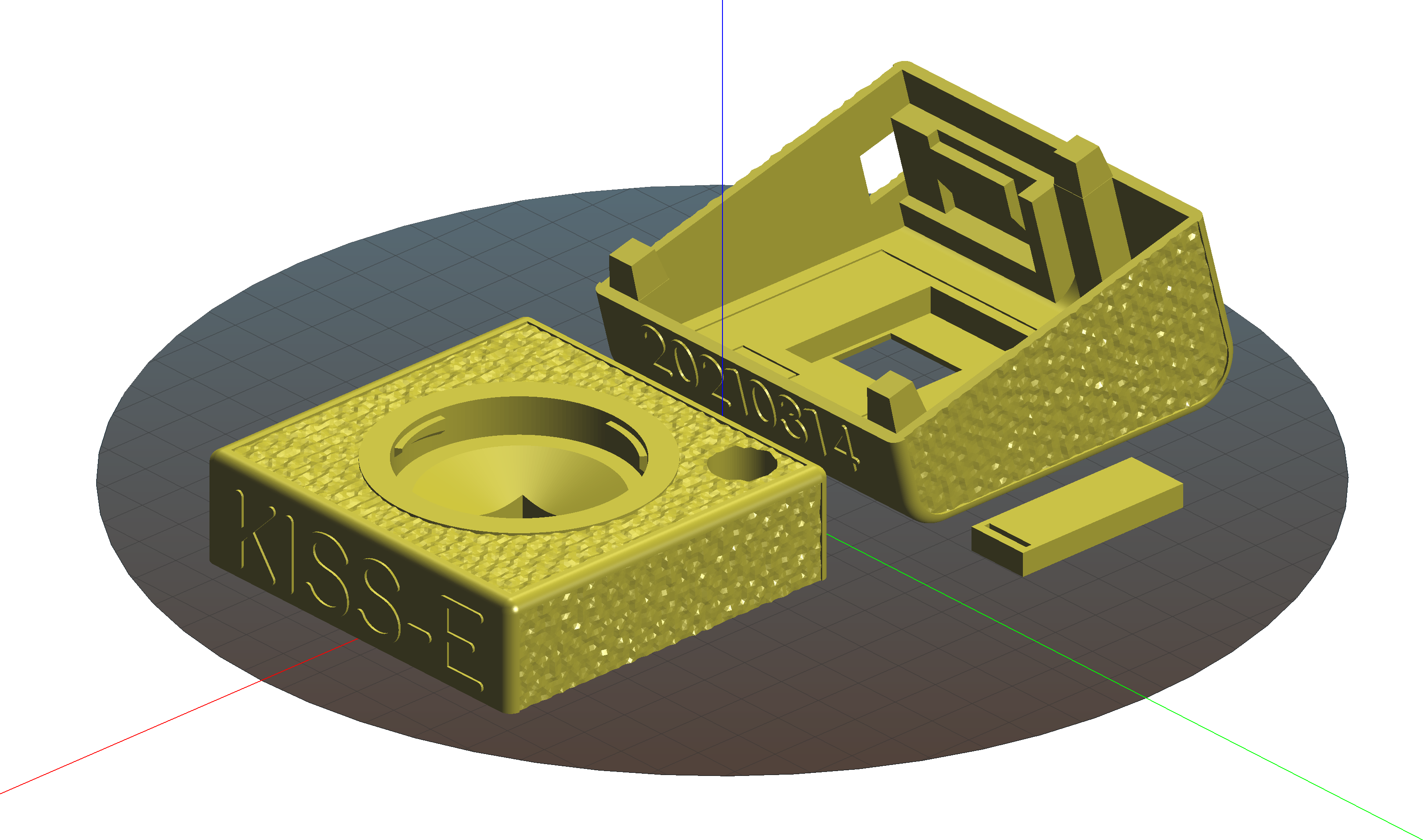
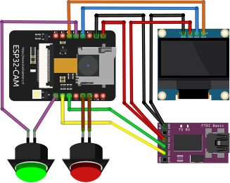
The latest version of the parts to 3D print for KISS-E is at https://www.printables.com/model/1855957-kiss-e-camera.
The surprisingly effective, yet rather crude, firmware for KISS-E is:
It is written for the ESP32 Arduino environment and must be modified to have the appropriate credentials for your 2.4GHz 802.11 network.
What do the images look like? Well, here is a simple image taken without NIR-blocking filter and a different image captured using the NIR-blocking filter:

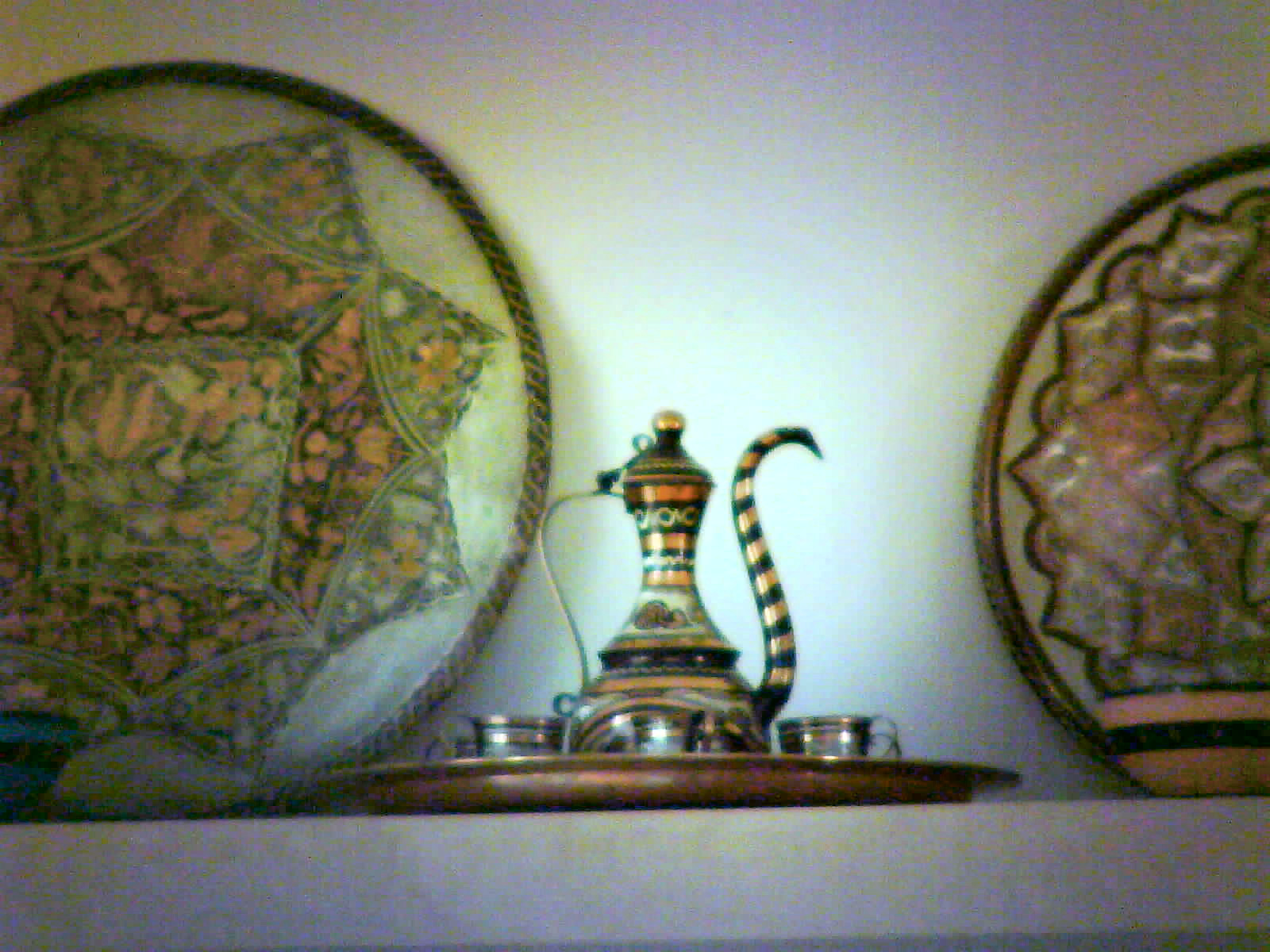
Neither of those images is very impressive, which is why there is now postkiss to clean-up the images...
Before describing the postkiss image postprocessing software, I need to give a couple of disclaimers: (1) postkiss is quite sophisticated, which makes it shockingly slow and (2) no matter how exotic the postprocessing, the image quality that can be obtained while being faithful to a scene captured with an OV2640 is not very impressive. I am making the C++ source code freely available under CC BY 4.0. Be warned that this software is "research grade" -- i.e., it works well enough to validate the concepts, but is by no means a carefully debugged, polished, or well-maintained production code. Here's the source code compressed tar:
Before describing the postkiss image postprocessing software, here are a few disclaimers. Postkiss is quite sophisticated, which makes it shockingly slow: it can take up to a minute to process each image. Still, no matter how exotic the postprocessing, the image quality that can be obtained while being faithful to a scene captured with an OV2640 is not very impressive. This software is also very far from a polished product; it's a somewhat messy research prototype based on an earlier research prototype called postkamf, which I created to maximize image quality of captures from either version of the KAMF modified kid's cameras that use 640x480 pixel sensors.
Here are a few simple postkiss command lines and what they do. In each case, the input images are expected to be in the usual unturned 1600x1200 orientation, and that's also how the output is generated. The output file is a 16BPP PNG named postkiss.png by default, which you can turn and process further with any image editor. The PNG output file tends to look darker than the original images due to gamma linearization for processing, but this is easily adjusted in your favorite image editor; the generated PNG is conceptually more like a raw image than a JPEG. Also, because we know the sensor is actually 1600x1200, postkiss internally scales all images to that size before operating on them.
./postkiss capture.jpg
Compute a statistical pixel value error model for the image capture.jpg and apply noise reduction using it; this is essentially a version of the kremy (KentuckY Raw Error Modeler) algorithm described in my Electronic Imaging 2022 paper, An improved raw image enhancement algorithm using a statistical model for pixel value error.
./postkiss -w white.jpg capture.jpg
Same as above, but first correct the image vignetting and color casts using the reference white image white.jpg, which should have been captured with similar camera settings of a featureless white surface, such as a blank white wall out of focus.
./postkiss -w white.jpg capture0.jpg capture1.jpg ...
Same as above, but also apply subpixel alignment to capture0.jpg using the set of images to create a default 2X (linear dimensions; 4X total pixel count) superresolution image. The captures are assumed to be taken with very little movement between shots; the processing was created for superresolution merging of pixel-shift image sequences, using the parsek (Probabilistic Alignment Raw Stitcher Experiment from Kentucky) algorithm as described in my Electronic Imaging 2024 paper, Leveraging Pixel Value Certainty in Pixel-Shift and Other Multi-Shot Super-Resolution Processing. The extreme effective focal lengths for KISS Viewer magnify tiny vibrations so that a sequence of shots typically has roughly the same magnitude of misalignments found in pixel-shift sequences.
You can see how effective postkiss is by looking at the photos at the end of the KISS Viewer section above. How much correction was necessary before the fancy processing? Quite a lot. Here's what the white.jpg used for those images looked like:

Note that postkiss expects images to be in the 1600x1200 landscape orientation, which is how the sensor outputs them. Very likely, your OV2640 module is turned 90 degrees, in which case you should turn the images output by postkiss, not the ones input to it.
If you have any comments or suggestions, you can send them to Professor Hank Dietz or, better still, post them at DPReview. A good place to post them would be A Tower-ing little project in the DIY forum.
KISS: Kentucky's Interchangeable lens Small Sensor cameras
 The only thing set in stone is our name.